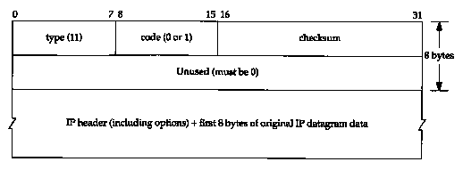
Figure 8.2 ICMP time exceeded message.
The Traceroute program, written by Van Jacobson, is a handy debugging tool that allows us to further explore the TCP/IP protocols. Although there are no guarantees that two consecutive IP datagrams from the same source to the same destination follow the same route, most of the time they do. Traceroute lets us see the route that IP datagrams follow from one host to another. Traceroute also lets us use the IP source route option.
The manual page states: "Implemented by Van Jacobson from a suggestion by Steve Deering. Debugged by a cast of thousands with particularly cogent suggestions or fixes from C. Philip Wood, Tim Seaver, and Ken Adelman."
8.2 Traceroute Program Operation
In Section 7.3 we described the IP record route option (RR). Why wasn't this used instead of developing a new application? There are three reasons. First, historically not all routers have supported the record route option, making it unusable on certain paths. (Traceroute doesn't require any special or optional features at any intermediate routers.)
Second, record route is normally a one-way option. The sender enables the option and the receiver has to fetch all the values from the received IP header and somehow return them to the sender. In Section 7.3 we saw that most implementations of the Ping server (the ICMP echo reply function within the kernel) reflect an incoming RR list, but this doubles the number of IP addresses recorded (the outgoing path and the return path), which runs into the limit described in the next paragraph. (Traceroute requires only a working UDP module at the destination-no special server application is required.)
The third and major reason is that the room allocated for options in the IP header isn't large enough today to handle most routes. There is room for only nine IP addresses in the IP header options field. In the old days of the ARPANET this was adequate, but it is far too small nowadays.
Traceroute uses ICMP and the TTL field in the IP header. The TTL field (time-to-live) is an 8-bit field that the sender initializes to some value. The recommended initial value is specified in the Assigned Numbers RFC and is currently 64. Older systems would often initialize it to 15 or 32. We saw in some of the Ping examples in Chapter 7 that ICMP echo replies are often sent with the TTL set to its maximum value of 255.
Each router that handles the datagram is required to decrement the TTL by either one or the number of seconds that the router holds onto the datagram. Since most routers hold a datagram for less than a second, the TTL field has effectively become a hop counter, decremented by one by each router.
RFC 1009 [Braden and Postel 1987] required a router that held a datagram for more than 1 second to decrement the TTL by the number of seconds. Few routers implemented this requirement. The new Router Requirements RFC [Almquist 1993] makes this optional, allowing a router to treat the TTL as just a hop count.
The purpose of the TTL field is to prevent datagrams from ending up in infinite loops, which can occur during routing transients. For example, when a router crashes or when the connection between two routers is lost, it can take the routing protocols some time (from seconds to a few minutes) to detect the lost route and work around it. During this time period it is possible for the datagram to end up in routing loops. The TTL field puts an upper limit on these looping datagrams.
When a router gets an IP datagram whose TTL is either 0 or 1 it must not forward the datagram. (A destination host that receives a datagram like this can deliver it to the application, since the datagram does not have to be routed. Normally, however, no system should receive a datagram with a TTL of 0.) Instead the router throws away the datagram and sends back to the originating host an ICMP "time exceeded" message. The key to Traceroute is that the IP datagram containing this ICMP message has the router's IP address as the source address.
We can now guess the operation of Traceroute. It sends an IP datagram with a TTL of 1 to the destination host. The first router to handle the datagram decrements the TTL, discards the datagram, and sends back the ICMP time exceeded. This identifies the first router in the path. Traceroute then sends a datagram with a TTL of 2, and we find the IP address of the second router. This continues until the datagram reaches the destination host. But even though the arriving IP datagram has a TTL of 1, the destination host won't throw it away and generate the ICMP time exceeded, since the datagram has reached its final destination. How can we determine when we've reached the destination?
Traceroute sends UDP datagrams to the destination host, but it chooses the destination UDP port number to be an unlikely value (larger than 30,000), making it improbable that an application at the destination is using that port. This causes the destination host's UDP module to generate an ICMP "port unreachable" error (Section 6.5) when the datagram arrives. All Traceroute needs to do is differentiate between the received ICMP messages-time exceeded versus port unreachable-to know when it's done.
The Traceroute program must be able to set the TTL field in the outgoing datagram. Not all programming interfaces to TCP/IP support this, and not all implementations support the capability, but most current systems do, and are able to run Traceroute. This programming interface normally requires the user to have superuser privilege, meaning it may take special privilege to run it on your host.
We're now ready to run traceroute and see the output. We'll use our simple internet (see the figure on the inside front cover) going from svr4 to slip, through the router bsdi. The hardwired SLIP link between bsdi and slip is 9600 bits/sec.
svr4 % traceroute slip
traceroute to slip (140.252.13.65), 30 hops max. 40
byte packets
1 bsdi (140.252.13.35) 20 ms 10
ms 10 ms
2 slip (140.252.13.65) 120 ms 120 ms 120 ms
The first unnumbered line of output gives the name and IP address of the destination and indicates that traceroute won't increase the TTL beyond 30. The datagram size of 40 bytes allows for the 20-byte IP header, the 8-byte UDP header, and 12 bytes of user data. (The 12 bytes of user data contain a sequence number that is incremented each time a datagram is sent, a copy of the outgoing TTL, and the time at which the datagram was sent.)
The next two lines in the output begin with the TTL, followed by the name of the host or router, and its IP address. For each TTL value three datagrams are sent. For each returned ICMP message the round-trip time is calculated and printed. If no response is received within 5 seconds for any of the three datagrams, an asterisk is printed instead and the next datagram is sent. In this output the first three datagrams had a TTL of 1 and the ICMP messages were returned in 20, 10, and 10 ms. The next three datagrams were sent with a TTL of 2 and the ICMP messages were returned 120 ms later. Since the TTL of 2 reached the final destination, the program then stopped.
The round-trip times are calculated by the traceroute program on the sending host. They are the total RTTs from the traceroute program to that router. If we're interested in the per-hop time we have to subtract the value printed for TTL N from the value printed for TTL N+1.
Figure 8.1 shows the tcpdump output for this run. As we might have guessed, the reason that the first probe packet to bsdi had an RTT of 20 ms and the next two had an RTT of 10 ms was because of an ARP exchange, tcpdump shows this is indeed the case.
The destination UDP port starts at 33435 and is incremented by one each time a datagram is sent. This starting port number can be changed with a command-line option. The UDP datagram contains 12 bytes of user data, which we calculated earlier when traceroute output that it was sending 40-byte datagrams.
Next, tcpdump prints the comment [ttl 1] when the IP datagram has a TTL of 1. It prints a message like this when the TTL is 0 or 1, to warn us that something looks funny in the datagram. Here we expect to see the TTL of 1, but with some other application it could be a warning that the datagram might not get to its final destination. We should never see a datagram passing by with a TTL of 0, unless the router that put it on the wire is broken.
| 1 | 0.0 | arp who-has bsdi tell svr4 |
| 2 | 0.000586 (0.0006) | arp reply bsdi is-at 0:0:c0:6f:2d:40 |
| 3 | 0.003067 (0.0025) | svr4.42804 > slip.33435; udp 12 [ttl 1] |
| 4 | 0.004325 (0.0013) | bsdi > svr4: icmp: time exceeded in-transit |
| 5 | 0.069810 (0.0655) | svr4.42804 > slip.33436: udp 12 [ttl 1] |
| 6 | 0.071149 (0.0013) | bsdi > svr4: icmp: time exceeded in-transit |
| 7 | 0.085162 (0.0140) | svr4.42804 > slip.33437: udp 12 [ttl 1] |
| 8 | 0.086375 (0.0012) | bsdi > svr4: icmp: time exceeded in-transit |
| 9 | 0.118608 (0.0322) | svr4.42804 > slip.33438: udp 12 |
| 10 | 0.226464 (0.1079) | slip > svr4: icmp: slip udp port 33438 unreachable |
| 11 | 0.287296 (0.0608) | svr4.42804 > slip.33439: udp 12 |
| 12 | 0.395230 (0.1079) | slip > svr4: icmp: slip udp port 33439 unreachable |
| 13 | 0.409504 (0.0143) | svr4.42804 > slip.33440: udp 12 |
| 14 | 0.517430 (0.1079) | slip > svr4: icmp: slip udp port 33440 unreachable |
The ICMP message "time exceeded in transit" is what we expect to see from the router bsdi, since it will decrement the TTL to 0. The ICMP message comes from the router even though the IP datagram that was thrown away was going to slip.
There are two different ICMP "time exceeded" messages (Figure 6.3), each with a different code field in the ICMP message. Figure 8.2 shows the format of this ICMP error message.
The one we've been describing is generated when the TTL reaches 0, and is specified by a code of 0.
It's also possible for a host to send an ICMP "time exceeded during reassembly" when it times out during the reassembly of a fragmented datagram. (We talk about fragmentation and reassembly in Section 11.5.) This error is specified by a code of 1.
Lines 9-14 in Figure 8.1 correspond to the three datagrams sent with a TTL of 2. These reach the final destination and generate an ICMP port unreachable message.
It is worthwhile to calculate what the round-trip times should be for the SLIP link, similar to what we did in Section 7.2 when we set the link to 1200 bits/sec for the Ping example. The outgoing UDP datagram contains 12 bytes of data, 8 bytes of UDP header, 20 bytes of IP header, and 2 bytes (at least) of SLIP framing (Section 2.4) for a total of 42 bytes. Unlike Ping, however, the size of the return datagrams changes. Recall from Figure 6.9 that the returned ICMP message contains the IP header of the datagram that caused the error and the first 8 bytes of data that followed that IP header (which is a UDP header in the case of traceroute). This gives us a total of 20+8+20+8+2, or 58 bytes. With a data rate of 960 bytes/sec the expected RTT is (42 + 58/960) or 104 ms. This corresponds to the IIO-ms value measured on svr4.
The source port number in Figure 8.1 (42804) seems high. traceroute sets the source port number of the UDP datagrams that it sends to the logical-OR of its Unix process ID with 32768. In case traceroute is being run multiple times on the same host, each process looks at the source port number in the UDP header that's returned by ICMP, and only handles those messages that are replies to probes that it sent.
There are several points to note with traceroute. First, there is no guarantee that the route today will be in use tomorrow, or even that two consecutive IP datagrams follow the same route. If a route changes while the program is running you'll see it occur because traceroute prints the new IP address for the given TTL if it changes.
Second, there is no guarantee that the path taken by the returned ICMP message retraces the path of the UDP datagram sent by traceroute. This implies that the round-trip times printed may not be a true indication of the outgoing and returning datagram times. (If it takes 1 second for the UDP datagram to travel from the source to a router, but 3 seconds for the ICMP message to travel a different path back to the source, the printed round-trip time is 4 seconds.)
Third, the source IP address in the returned ICMP message is the IP address of the interface on the router on which the UDP datagram arrived. This differs from the IP record route option (Section 7.3), where the IP address recorded was the outgoing interface's address. Since every router by definition has two or more interfaces, running traceroute from host A to host B can generate different output than from host B to host A. Indeed, if we run traceroute from host slip to svr4 the output becomes:
slip % traceroute svr4
traceroute to svr4 (140.252.13.34), 30 hops max, 40
byte packets
1 bsdi (140.252.13.66) 110 ms
110 ms 110 ms
2 svr4 (140.252.13.34) 110 ms 120 ms 110 ms
This time the IP address printed for host bsdi is 140.252.13.66, the SLIP interface, while previously it was 140.252.13.35, the Ethernet interface. Since traceroute also tries to print the name associated with an IP address, the names can change. (In our example both interfaces on bsdi have the same name.)
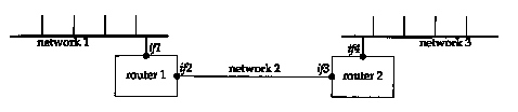
Consider Figure 8.3. It shows two local area networks with a router connected to each LAN. The two routers are connected with a point-to-point link. If we run traceroute from a host on the left LAN to a host on the right LAN, the IP addresses found for the routers will be if1 and if3. But going the other way will print the IP addresses if4 and if2. The two interfaces if2 and if3 share the same network ID, while the other two interfaces have different network IDs.
Finally, across wide area networks the traceroute
output is much easier to comprehend if the IP addresses are printed
as readable domain names, instead of as IP addresses. But since
the only piece of information traceroute
has when it receives the ICMP message is an IP address, it does
a "reverse name lookup" to find the name, given the
IP address. This requires the administrator responsible for that
router or host to configure their reverse name lookup function
correctly (which isn't always the case). We describe how an IP
address is converted to a name using the DNS in Section 14.5.
8.4 WAN Output
The output shown earlier for our small internet is adequate for examining the protocols in action, but more a realistic use of traceroute involves larger internets such as the worldwide Internet. Figure 8.4 is from the host sun to the Network Information Center, the NIC.
sun % traceroute nic.ddn.mil
traceroute to nic.ddn.mil (192.112.36.5), 30 hops max,
40 byte packets
1 netb.tuc.noao.edu (140.252.1.183) 218
ms 227 ms 233 ms
2 gateway.tuc.noao.edu (140.252.1.4) 233 ms 229 ms 204 ms
3 butch.telcom.arizona.edu (140.252.104.2) 204 ms 228 ms 234
ms
4 Gabby.Telcom.Arizona.EDU (128.196.128.1)
234 ms 228 ms 204 ms
5 NSIgate.Telcom.Arizona.EDU (192.80.43.3) 233 ms 228 ms 234 ms
6 JPLI.NSN.NASA.GOV (128.161.88.2) 234 ms 590 ms 262 ms
7 JPL3.NSN.NASA.GOV (192.100.15.3)
238 ms 223 ms 234 ms
8 GSFC3.NSN.NASA.GOV (128.161.3.33) 293 ms 318 ms 324 ms
9 GSFC8.NSN.NASA.GOV (192.100.13.8) 294 ms 318 ms 294 ms
10 SURA2.NSN.NASA.GOV (128.161.166.2) 323 ms 319 ms 294 ms
11 nsn-FIX-pe.sura.net (192.80.214.253) 294 ms 318 ms 294 ms
12 GSI.NSN.NASA.GOV (128.161.252.2) 293 ms 318 ms 324 ms
13 NIC.DDN.MIL (192.112.36.5) 324 ms 321 ms 324 ms
Since running this example for inclusion in the text, the NIC for non-DDN sites (i.e., nonmilitary) has moved from nic.ddn.mil to rs.internic.net, the new "InterNIC."
Once the datagrams leave the tuc.noao.edu network they enter the telcom.arizona.edu network. They then enter the NASA Science Internet, nsn.nasa.gov. The routers for TTLs 6 and 7 are at the Jet Propulsion Laboratory (JPL). The network sura. net in the output for TTL II is the Southeastern Universities Research Association Network. The name GSI at TTL 12 is Government Systems, Inc., the operator of the NIC.
The second RTT for the TTL of 6 (590) is almost double the other two RTTs (234 and 262). This illustrates the dynamics of IP routing. Something happened somewhere between the sending host and this router that slowed down this datagram. Also, we can't tell if it was the outbound datagram that got held up or the return ICMP error.
The RTT for the first probe with a TTL of 3 (204) is less than the RTT for the first probe with a TTL of 2 (233). Since each printed RTT is the total time from the sending host to that router, this can (and does) happen. The example in Figure 8.5 is from the host sun to the author's publisher.
sun % traceroute aw.com
traceroute to aw.com (192.207.117.2), 30 hops max, 40 byte packets
1 netb.tuc.noao.edu (140.252.1.183) 227 ms 227 ms 234 ms
2 gateway.tuc.noao.edu (140.252.1.4)
233 ms 229 ms 234 ms
3 butch.telcom.arizona.edu (140.252.104.2) 233 ms 229 ms 234 ms
4 Gabby.Telcom.Arizona. EDU (128.196.128.1) 264 ms 228 ms 234
ms
5 Westgate.Telcom.Arizona. EDO (192.80.43.2) 234 ms 228 ms 234
ms
6 uu-ua.AZ.westnet.net (192.31.39.233) 263 ms 258 ms 264 ms
7 enssl42.UT.westnet.net (192.31.39.21) 263 ms 258 ms 264 ms
8 t3-2.Denver-cnss97.t3.ans.net (140.222.97.3) 293 ms 288 ms 275
ms
9 t3-3.Denver-cnss96.t3.ans.net (140.222.96.4) 283 ms 263 ms 261
ms
10 t3-1.St-Louis-cnss80.t3.ans.net (140.222.80.2) 282 ms 288 ms
294 ms
11 t3-1.Chicago-cnss24.t3.ans.net (140.222.24.2) 293 ms 288 ms
294 ms
12 t3-2.Cleveland-cnss40.t3.ans.net (140.222.40.3) 294 ms 288
ms 294 ms
13 t3-1.New-York-cnss32.t3.ans.net (140.222.32.2) 323 ms 318 ms
324 ms
14 t3-1.Washington-DC-cnss56.t3.ans.net (140.222.56.2) 323 ms
318 ms 324 ms
15 t3-0.Washington-DC-cnss58.t3.ans.net (140.222.58.1) 324 ms
318 ms 324 ms
16 t3-0.enssl36.t3.ans.net (140.222.136.1) 323 ms 318 ms 324 ms
17 Washington.DC.ALTER.NET (192.41.177.248) 323 ms 377 ms 324
ms
18 Boston.MA.ALTER.NET (137.39.12.2) 324 ms 347 ms 324 ms
19 AW-gw.ALTER.NET (137.39.62.2) 353 ms 378 ms 354 ms
20 aw.com (192.207.117.2) 354 ms 349 ms 354 ms
This time the datagrams enter the regional network
westnet.net (TTLs 6 and 7) after
leaving the telcom.arizona.edu network.
They then enter the NSFNET backbone, t3.ans.net,
which is run by Advanced Network & Services. (T3 is the common
abbreviation for the 45 Mbits/sec phone lines used by the backbone.)
The final network is alter.net, the
connection point to the Internet for aw.corn.
8.5 IP Source Routing Option
Normally IP routing is dynamic with each router making a decision about which next-hop router to send the datagram to. Applications have no control of this, and are normally not concerned with it. It takes tools such as Traceroute to figure out what the route really is.
The idea behind source routing is that the sender specifies the route. Two forms are provided:
Traceroute provides a way to look at source routing, as we can specify an option allowing us to force a source route, and see what happens.
Some of the publicly available Traceroute source code packages contain patches to specify loose source routing. But the standard versions normally don't include this option. A comment in the patches is that "Van Jacobson's original traceroute (spring 1988) supported this feature, but he removed it due to pressure from people with broken gateways." For the examples shown in this section, the author installed these patches and modified them to allow both loose and strict source routing.
Figure 8.6 shows the format of the source route option.
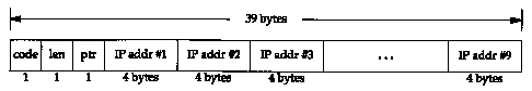
This format is nearly identical to the format of the record route option that we showed in Figure 7.3. But with source routing we have to fill in the list of IP addresses before sending the IP datagram, while with the record route option we allocate room and zero out the list of IP addresses, letting the routers fill in the next entry in the list. Also, with source routing we only allocate room for and initialize the number of IP addresses required, normally fewer than nine. With the record route option we allocated as much room as we could, for up to nine addresses.
The code is 0x83 for loose source routing, and 0x89 for strict source routing. The len and ptr fields are identical to what we described in Section 7.3.
The source route options are actually called "source and record route" (LSRR and SSRR, for loose and strict) since the list of IP addresses is updated as the datagram passes along the path. What happens is as follows:
This is best explained with an example. In Figure 8.7 we assume that the sending application on host S sends a datagram to D, specifying a source route of R1, R2, and R3.
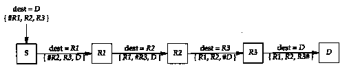
In this figure the pound sign (#) denotes the pointer field, which assumes the values of 4, 8, 12, and 16. The length field will always be 15 (three IP addresses plus 3 bytes of overhead). Notice how the destination address of the IP datagram changes on every hop.
When an application receives data that was source routed, it should fetch the value of the received route and supply a reversed route for sending replies.
The Host Requirements RFC specifies that a TCP client must be able to specify a source route, and that a TCP server must be able to receive a source route, and use the reverse route for all segments on that TCP connection. If the TCP server later receives a different source route, that newer source route overrides the earlier one.
The -g option to traceroute lets us specify intermediate routers to be used with loose source routing. This option can be specified up to eight times. (The reason this is eight and not nine is that the programming interface being used requires that the final entry be the destination.)
Recall from Figure 8.4 that the route to the NIC, nic.ddn.mil, was through the NASA Science Internet. In Figure 8.8 we force the datagrams to pass through the NSFNET instead by specifying the router enssl42.UT.westnet.net (192.31.39.21) as an intermediate router:
sun % traceroute -g 192.31.39.21
nic.ddn.mil
traceroute to nic.ddn.mil (192.112.36.5), 30 hops max, 40 byte
packets
1 netb.tuc.noao.edu (140.252.1.183) 259 ms 256 ms 235 ms
2 butch.telcom.arizona.edu (140.252.104.2)
234 ms 228 ms 234 ms
3 Gabby.Telcom.Arizona.EDU (128.196.128.1) 234 ms 257 ms 233 ms
4 enssl42.UT.westnet.net (192.31.39.21) 294 ms 288 ms 295 ms
5 t3-2.Denver-cnss97.t3.ans.net (140.222.97.3) 294 ms 286 ms 293
ms
6 t3-3.Denver-cnss96.t3.ans.net (140.222.96.4) 293 ms 288 ms 294
ms
7 t3-1.St-Louis-cnss80.t3.ans.net (140.222.80.2) 294 ms 318 ms
294 ms
8 * t3-1.Chicago-cnss24.t3.ans.net (140.222.24.2) 318 ms 295 ms
9 t3-2.Cleveland-cnss40.t3.ans.net (140.222.40.3) 319 ms 318 ms
324 ms
10 t3-1.New-York-cnss32.t3.ans.net (140.222.32.2) 324 ms 318 ms
324 ms
11 t3-1.Washington-DC-cnss56.t3.ans.net (140.222.56.2) 353 ms
348 ms 325 ms
12 t3-0.Washington-DC-cnss58.t3.ans.net (140.222.58.1) 348 ms
347 ms 325 ms
13 13-0. enssl45.t3.ans. net (140.222.145.1) 353 ms 348 ms 325
ms
14 nsn-FIX-pe.sura.net (192.80.214.253) 353 ms 348 ms 325 ms
15 GSI.NSN.NASA.GOV (128.161.252.2) 353 ms 348 ms 354 ms
16 NIC.DDN.MIL (192.112.36.5) 354 ms 347 ms 354 ms
This time there appear to be 16 hops with an average RTT of around 350 ms, while the normal route shown in Figure 8.4 had only 13 hops and an average RTT of around 322 ms. The default route appears better. (There are also other decisions made when routes are established. Some are made on the basis of the organizational and political boundaries of the networks involved.)
But we said there appear to be 16 hops, because a comparison of this output with our previous example through the NSFNET (Figure 8.5) shows three missing routers in this example using loose source routing. (These are probably caused by bugs in the router's generation of ICMP time exceeded errors in response to source routed datagrams.) The router gateway.tuc.noao.edu is missing between netb and butch, and the routers Westgate.Telcom.Arizona.edu and uu-ua.AZ.westnet.net are also missing between Gabby and enssl42.UT.westnet.net. There is probably a software problem in these missing routers related to incoming datagrams with the loose source routing option. There are really 19 hops between the source and the NIC, when using the NSFNET. Exercise 8.5 continues the discussion of these missing routers.
This example also illustrates another problem. On the command line we have to specify the dotted-decimal IP address of the router enssl42.UT.westnet.net instead of its name. This is because the reverse name lookup (return the name, given the IP address. Section 14.5), associates the name with the IP address, but the forward lookup (given the name, return the IP address) fails. The forward mapping and reverse mapping are two separate files in the DNS (Domain Name System) and not all administrators keep the two synchronized with each other. It's not uncommon to have one direction work and the other direction fail.
Something that we haven't seen before is the asterisk (*) printed for the first RTT for the TTL of 8. This indicates that a timeout occurred and no response was received within 5 seconds for this probe.
Another point that we can infer from a comparison of this figure and Figure 8.4 is that the router nsn-FIX-pe.sura.net is connected to both the NSFNET and the NASA Science Internet.
The -G option in the author's version of traceroute is identical to the -g option described earlier, but the source route is strict instead of loose. We can use this to see what happens when an invalid strict source route is specified. Recall from Figure 8.5 that the normal sequence of routers for datagrams from the author's subnet to the NSFNET is through netb, gateway, butch, and gabby. (We've omitted the domain suffixes, .tuc.noao.edu and .telcom.arizona.edu, in all the output below to make it easier to read.) We specify a strict source route that omits butch, trying to go directly from gateway to gabby. We expect this to fail, as shown in Figure 8.9.
sun % traceroute -G netb
-G gateway -G gabby westgate
traceroute to westgate (192.80.43.2), 30 hops max.
40 byte packets
1 netb (140.252.1.183) 272 ms 257 ms 261 ms
2 gateway (140.252.1.4) 263 ms
259 ms 234 ms
3 gateway (140.252.1.4) 263 ms !S * 235 ms !S
The key here is the notation ! s following the RTTs for the TTL of 3. This indicates that traceroute received an ICMP "source route failed" error message: a type of 3 and a code of 5 from Figure 6.3. The asterisk for the second RTT for the TTL of 3 indicates no response was received for that probe. This is what we expect, since it's impossible for gateway to send the datagram directly to gabby, because they're not directly connected.
The reason that both TTLs 2 and 3 are from gateway is that the values for the TTL of 2 are from gateway when it receives the datagram with an incoming TTL of 1. It discovers that the TTL has expired before it looks at the (invalid) strict source route, and sends back the ICMP time exceeded. The line with a TTL of 3 is received by gateway with an incoming TTL of 2, so it looks at the strict source route, discovers that it's invalid, and sends back the ICMP source route failed error.
Figure 8.10 shows the tcpdump output corresponding to this example. This output was collected on the SLIP link between sun and netb. We had to specify the -v option for tcpdump to display the source route information. This produces other output that we don't need, such as the datagram ID, which we've deleted. Also, the notation SSRR stands for "strict source and record route."
| 1 | 0.0 | sun.33593 > netb.33435: udp 12 [ttl 1]
(optlen=16 SSRR{#gateway gabby westgate} EOL) |
| 2 | 0.270278 (0.2703) | netb > sun: icmp: time exceeded in-transit |
| 3 | 0.284784 (0.0145) | sun.33593 > netb.33436: udp 12 [ttl 1]
(optlen=16 SSRR{#gateway gabby westgate} EOL) |
| 4 | 0.540338 (0.2556) | netb > sun: icmp: time exceeded in-transit |
| 5 | 0.550062 (0.0097) | sun.33593 > netb.33437: udp 12 [ttl 1]
(optlen=16 SSRR(#gateway gabby westgate} EOL) |
| 6 | 0.810310 (0.2602) | netb > sun: icmp: time exceeded in-transit |
| 7 | 0.818030 (0.0077) | sun.33593 > netb.33438: udp 12 (ttl 2,
optlen=16 SSRR(#gateway gabby westgate} EOL) |
| 8 | 1.080337 (0.2623) | gateway > sun: icmp: time exceeded in-transit |
| 9 | 1.092564 (0.0122) | sun.33593 > netb.33439: udp 12 (ttl 2,
optlen=16 SSRR{#gateway gabby westgate} EOL) |
| 10 | 1.350322 (0.2578) | gateway > sun: icmp: time exceeded in-transit |
| 11 | 1.357382 (0.0071) | sun.33593 > netb.33440: udp 12 (ttl 2,
optlen=16 SSRR(#gateway gabby westgate} EOL) |
| 12 | 1.590586 (0.2332) | gateway > sun: icmp: time exceeded in-transit |
| 13 | 1.598926 (0.0083) | sun.33593 > netb.33441: udp 12 (ttl 3,
optlen=16 SSRR{#gateway gabby westgate} EOL) |
| 14 | 1.860341 (0.2614) | gateway > sun:
icmp: gateway unreachable - source route failed |
| 15 | 1.875230 (0.0149) | sun.33593 > netb.33442: udp 12 (ttl 3,
optlen=16 SSRR{#gateway gabby westgate} EOL) |
| 16 | 6.876579 (5.0013) | sun.33593 > netb.33443: udp 12 (ttl 3,
optlen=16 SSRR{#gateway gabby westgate} EOL) |
| 17 | 7.110518 (0.2339) | gateway > sun:
icmp: gateway unreachable - source route failed |
First note that each UDP datagram sent by sun has a destination of netb, not the destination host (westgate). We described this with the example shown in Figure 8.7. Similarly, the other two routers specified with the -G option (gateway and gabby) and the final destination (westgate) become the SSRR option list on the first hop.
We can also see from this output that the timeout used by traceroute (the time difference between lines 15 and 16) is 5 seconds.
Earlier we said that there is no guarantee that the route from A to Bis the same as the route from B to A. Other than having a login on both systems and running traceroute on each end, it's hard to find out if there is a difference in the two paths. Using loose source routing, however, we can determine the route in both directions.
The trick is to specify loose source routing with the destination as the loose route, and the sending host as the final destination. For example, on the host sun we can find the paths to and from the host bruno.cs.colorado.edu (Figure 8.11) .
sun % traceroute -g bruno.cs.colorado.edu
sun
traceroute to sun (140.252.13.33), 30 hops max, 40 byte packets
1 netb.tuc.noao.edu (140.252.1.183) 230 ms 227 ms 233 ms
2 gateway.tuc.noao.edu (140.252.1.4)
233 ms 229 ms 234 ms
3 butch.telcom.arizona.edu (140.252.104.2) 234 ms 229 ms 234 ms
4 Gabby.Telcom.Arizona.EDU (128.196.128.1) 233 ms 231 ms 234 ms
5 NSIgate.Telcom.Arizona.EDU (192.80.43.3) 294 ms 258 ms 234 ms
6 JPLI.NSN.NASA.GOV (128.161.88.2) 264 ms 258 ms 264 ms
7 JPL2.NSN.NASA.GOV (192.100.15.2) 264 ms 258 ms 264 ms
8 NCAR.NSN.NASA.GOV (128.161.97.2) 324 ms * 295 ms
9 cu-gw.ucar.edu (192.43.244.4) 294 ms 318 ms 294 ms
10 engr-gw.Colorado.EDU (128.138.1.3) 294 ms 288 ms 294 ms
11 bruno.cs.Colorado.edu (128.138.243.151) 293 ms 317 ms 294 ms
12 engr-gw-ot.cs.Colorado.edu (128.138.204.1) 323 ms 317 ms 384
ms
13 cu-gw.Colorado.EDU (128.138.1.1) 294 ms 318 ms 294 ms
14 enss.ucar.edu (192.43.244.10) 323 ms 318 ms 294 ms
15 t3-1.Denver-cnss97.t3.ans.net (140.222.97.2) 294 ms 288 ms
384 ms
16 t3-0.enssl42.t3.ans.net (140.222.142.1) 293 ms 288 ms 294 ms
17 Gabby.Telcom.Arizona.EDU (192.80.43.1) 294 ms 288 ms 294 ms
18 Butch.Telcom.Arizona.EDU (128.196.128.88) 293 ms 317 ms 294
ms
19 gateway.tuc.noao.edu (140.252.104.1) 294 ms 289 ms 294 ms
20 netb.tuc.noao.edu (140.252.1.183) 324 ms 321 ms 294 ms
21 sun.tuc.noao.edu (140.252.13.33) 534 ms 529 ms 564 ms
The outbound path (TTLs 1-11) differs from the return path (TTLs 11-21), a good illustration that Internet routing need not be symmetrical.
This output also illustrates the point we discussed
with Figure 8.3. Compare the output for TTLs 2 and 19: both are
for the router gateway.tuc.noao.edu,
but the two IP addresses are different. Since traceroute
identifies the incoming interface, and since we're passing through
the router in two different directions, once on the outbound path
(TTL 2) and then on the return path (TTL 19), we expect this.
We see the same effect comparing TTLs 3 and 18, and TTLs 4 and
17.
8.6 Summary
Traceroute is an indispensable tool when working with a TCP/IP network. Its operation is simple: send UDP datagrams starting with a TTL of 1, increasing the TTL by 1, to locate each router in the path. An ICMP time exceeded is returned by each router when it discards the UDP datagram, and an ICMP port unreachable is generated by the final destination.
We ran examples of traceroute on both LANs and WANs, and used it to examine IP source routing. We used loose source routing to see if the route to a destination is the same as the return route from that destination.
8.1 What can happen if an IP implementation decrements the incoming TTL and then tests for equal to 0?
8.2 How does traceroute calculate the RTT? Compare this to the RTT calculation done by ping.
8.3 (This exercise and the next one are based on actual problems determined when traceroute was being developed, and are from comments in the traceroute source code.) Assume there are three routers (Rl, R2, and R3) between the source and destination and that the middle router (R2) decrements the TTL but incorrectly forwards the IP datagram when the incoming TTL was 1. Describe what happens. How can you see this occur when running traceroute?
8.4 Again assume there are three routers between the source and destination. This time the destination host has a bug whereby it always uses the incoming TTL as the outgoing TTL of an ICMP message. Describe what happens and how you would see this.
8.5 We can run tcpdump on the SLIP link between sun and netb when running the example from Figure 8.8. If we specify the -v option we can see the TTL value of the returned ICMP messages. Doing this shows the incoming TTL from netb to be 255, from butch it's 253, from Gabby it's 252, and from enssl42.UT.westnet.net it's 249. Does this give any additional information about whether there really are some missing routers?
8.6 Both SunOS and SVR4 provide a version of ping with a -l option that provides a loose source route. The manual pages state that it's intended to be used with the -R option (which specifies the record route option). If you have access to either of these systems, try these two options together. What's happening? If you can watch the datagrams with tcpdump, describe what's going on.
8.7 Compare the ways ping and traceroute handle multiple instances of the client on the same host.
8.8 Compare the ways ping and traceroute measure the round-trip time.
8.9 We said traceroute picks the starting UDP destination port number at 33435 and increments this by one for each packet sent. In Section 1.9 we said ephemeral port numbers are normally between 1024 and 5000, making it unlikely that Traceroute's destination port is in use on the destination host. Is this still true under Solaris 2.2? (Hint: Read Section E.4.)
8.10 Read RFC 1393 [Malkin
1993b] for a proposed alternative way of determining the path
to a destination. What are its advantages and disadvantages?