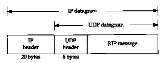
Figure 10.2 RIP message encapsulated within a UDP datagram.
Our discussion in the previous chapter dealt with static routing. The routing table entries were created by default when an interface was configured (for directly connected interfaces), added by the route command (normally from a system bootstrap file), or created by an ICMP redirect (usually when the wrong default was used).
This is fine if the network is small, there is a single connection point to other networks, and there are no redundant routes (where a backup route can be used if a primary route fails). If any of these three conditions is false, dynamic routing is normally used.
This chapter looks at the dynamic routing protocols
used by routers to communicate with each other. We concentrate
on RIP, the Routing Information Protocol, a widely used protocol
that is provided with almost every TCP/IP implementation. We then
look at two newer routing protocols, OSPF and BGP. The chapter
finishes with an examination of a new routing technique, called
classless interdomain routing, that is starting to be implemented
across the Internet to conserve class B network numbers.
10.2 Dynamic Routing
Dynamic routing occurs when routers talk to adjacent routers, informing each other of what networks each router is currently connected to. The routers must communicate using a routing protocol, of which there are many to choose from. The process on the router that is running the routing protocol, communicating with its neighbor routers, is usually called a routing daemon. As shown in Figure 9.1, the routing daemon updates the kernel's routing table with information it receives from neighbor routers.
The use of dynamic routing does not change the way the kernel performs routing at the IP layer, as we described in Section 9.2. We called this the routing mechanism. "The kernel still searches its routing table in the same way, looking for host routes, network routes, and default routes. What changes is the information placed into the routing table-instead of coming from route commands in bootstrap files, the routes are added and deleted dynamically by a routing daemon, as routes change over time.
As we mentioned earlier, the routing daemon adds a routing policy to the system, choosing which routes to place into the kernel's routing table. If the daemon finds multiple routes to a destination, the daemon chooses (somehow) which route is best, and which one to insert into the kernel's table. If the daemon finds that a link has gone down (perhaps a router crashed or a phone line is out of order), it can delete the affected routes or add alternate routes that bypass the problem.
In a system such as the Internet, many different routing protocols are currently used. The Internet is organized into a collection of autonomous systems (ASs), each of which is normally administered by a single entity. A corporation or university campus often defines an autonomous system. The NSFNET backbone of the Internet forms an autonomous system, because all the routers in the backbone are under a single administrative control.
Each autonomous system can select its own routing protocol to communicate between the routers in that autonomous system. This is called an interior gateway protocol (IGP) or intradomain routing protocol. The most popular IGP has been the Routing Information Protocol (RIP). A newer IGP is the Open Shortest Path First protocol (OSPF). It is intended as a replacement for RIP. An older IGP that has fallen out of use is HELLO-the IGP used on the original NSFNET backbone in 1986.
The new Router Requirements RFC [Almquist 1993] states that a router that implements any dynamic routing protocol must support both OSPF and RIP, and may support other IGPs.
Separate routing protocols called exterior gateway
protocols (EGPs) or interdomain routing protocols are
used between the routers in different autonomous systems. Historically
(and confusingly) the predominant EGP has been a protocol of the
same name: EGP A newer EGP is the Border Gateway Protocol (BGP)
that is currently used between the NSFNET backbone and some of
the regional networks that attach to the backbone. BGP is intended
to replace EGP.
10.3 Unix Routing Daemons
Unix systems often run the routing daemon named routed. It is provided with almost every implementation of TCP/IP This program communicates using only RIP, which we describe in the next section. It is intended for small to medium-size networks.
An alternative program is gated. It supports both IGPs and EGPs. [Fedor 1988] describes the early development of gated. Figure 10.1 compares the various routing protocols supported by routed and two different versions of gated. Most systems that run a routing daemon run routed, unless they need support for the other protocols supported by gated.
| routed | |||||
| gated, Version 2 | |||||
| gated, Version 3 | |||||
We describe RIP Version I in the next section, the
differences with RIP Version 2 in Section 10.5,
OSPF in Section 10.6, and BGP in Section 10.7.
10.4 RIP: Routing Information Protocol
This section provides an overview of RIP, because it is the most widely used (and most often maligned) routing protocol. The official specification for RIP is RFC 1058 [Hedrick 1988a], but this RFC was written years after the protocol was widely implemented.
RIP messages are carried in UDP datagrams, as shown in Figure 10.2. (We talk more about UDP in Chapter 11.)
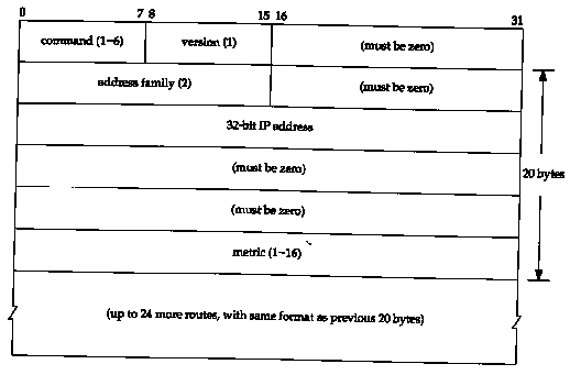
Figure 10.3 shows the format of the RIP message, when used with IP addresses.
A command of 1 is a request, and 2 is a reply. There are two other obsolete commands (3 and 4), and two undocumented ones: poll (5) and poll-entry (6). A request asks the other system to send all or part of its routing table. A reply contains all or part of the sender's routing table.
The version is normally 1, although RIP Version 2 (Section 10.5) sets this to 2.
The next 20 bytes specify the address family (which is always 2 for IP addresses), an IP address, and an associated metric. We'll see later in this section that RIP metrics are hop counts.
Up to 25 routes can be advertised in a RIP message using this 20-byte format. The limit of 25 is to keep the total size of the RIP message, 20 x 25+4 = 504, less than 512 bytes. With this limit of 25 routes per message, multiple messages are often required to send an entire routing table.
Let's look at the normal operation of routed, using RIP. The well-known port number for RIP is UDP port 520.
Each route has a timeout associated with it. If a system running RIP finds a route that has not been updated for 3 minutes, that route's metric is set to infinity (16) and marked for deletion. This means we have missed six of the 30-second updates from the router that advertised that route. The deletion of the route from the local routing table is delayed for another 60 seconds to ensure the invalidation is propagated.
The metrics used by RIP are hop counts. The hop count for all directly connected interfaces is 1. Consider the routers and networks shown in Figure 10.4. The four dashed lines we show are broadcast RIP messages.
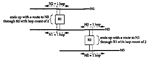
Router Rl advertises a route to N2 with a hop count of 1 by sending a broadcast on Nl. (It makes no sense to advertise a route to Nl in the broadcast sent on Nl.) It also advertises a route to Nl with a hop count of 1 by sending a broadcast on N2. Similarly, R2 advertises a route to N2 with a metric of 1, and a route to N3 with a metric of 1.
If an adjacent router advertises a route to another network with a hop count of 1, then our metric for that network is 2, since we have to send a packet to that router to get to the network. In our example, the metric to Nl for R2 is 2, as is the metric to N3 for Rl.
As each router sends its routing tables to its neighbors, a route can be determined to each network within the AS. If there are multiple paths within the AS from a router to a network, the router selects the path with the smallest hop count and ignores the other paths.
The hop count is limited to 15, meaning RIP can be used only within an AS where the maximum number of hops between hosts is 15. The special metric of 16 indicates that no route exists to the IP address.
As simple as this sounds, there are pitfalls. First, RIP has no knowledge of subnet addressing. If the normal 16-bit host ID of a class B address is nonzero, for example, RIP can't tell if the nonzero portion is a subnet ID or if the IP address is a complete host address. Some implementations use the subnet mask of the interface through which the RIP information arrived, which isn't always correct.
Next, RIP takes a long time to stabilize after the failure of a router or a link. The time is usually measured in minutes. During this settling time routing loops can occur. There are many subtle details in the implementation of RIP that must be followed to help prevent routing loops and to speed convergence. RFC 1058 [Hedrick 1988a] contains many details on how RIP should be implemented.
The use of the hop count as the routing metric omits other variables that should be taken into consideration. Also, a maximum of 15 for the metric limits the sizes of networks on which RIP can be used.
We'll use the program ripquery, which is available from the gated distribution, to query some routers for their routing table, ripquery tries to send one of the undocumented requests (named "poll," a command of 5 from Figure 10.3) to the router, asking for its entire routing table. If no response is received in 5 seconds, the standard RIP request is issued (command of 1). (Earlier we said a request with the family set to 0 and the metric set to 16 asks the other router for its entire routing table.)
Figure 10.5 shows the two routers that we'll query for their routing table from the host sun. If we execute ripquery from sun, fetching the routing information from its next-hop router, netb, we get the following:
| sun % ripquery -n netb 504 bytes from netb (140.252.1.183): 140.252.1.0, metric 1 140.252.13.0, metric 1 244 bytes from netb (140.252.1.183): | first message contains 504 bytes lots of other lines deleted the top Ethernet in Figure 10.5 the bottom Ethernet in Figure 10.5 second message with remaining 244 bytes lots of other lines deleted |
As we expect, the metric for our subnet that is announced by netb is 1. Additionally, the top Ethernet that netb is also attached to (140.252.1.0) has a metric of 1. (The -n flag says to print the IP addresses numerically instead of trying to look up the names.) In this example netb has been configured to consider all the hosts on the subnet 140.252.13 as directly connected to it - that is, netb knows nothing about which hosts are actually on the 140.252.13 subnet. Since there is only one connection point to the 140.252.13 subnet, advertising different metrics for each host makes little practical sense.
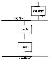
Figure 10.6 shows the packet exchange using tcpdump. We specify the SLIP interface with the -i sl0 option.
| sun % tcpdump s600 i sl0 | ||
| 1 | 0.0 | sun.2879 > netb.route: rip-poll 24 |
| 2 | 5.014702 (5.0147) | sun.2879 > netb.route: rip-req 24 |
| 3 | 5.560427 (0.5457) | netb.route > sun.2879: rip-resp 25: |
| 4 | 5.710251 (0.1498) | netb.route > sun.2879: rip-resp 12: |
The first request issued is the RIP poll command (line 1). This times out after 5 seconds and a normal RIP request is issued (line 2). The number 24 at the end of lines 1 and 2 is the size of the request packets in bytes: the 4-byte RIP header (with the command and version) followed by a single 20-byte address and metric.
Line 3 is the first reply message. The number 25 at the end indicates that 25 address and metric pairs are in the message, which we calculated earlier to be 504 bytes. This is what ripquery printed above. We specified the -s600 option to tcpdump telling it to read 600 bytes from the network. This allows it to receive the entire UDP datagram (instead of just the first portion of it) and it then prints the contents of the RIP response. We've omitted that output.
Line 4 is the second response message from the router, with the next 12 address and metric pairs. We can calculate the size of this message to be 12 x 20 + 4 = 244, which is what ripquery printed earlier.
If we go one router beyond netb, to gateway, we expect the metric to our subnet (140.252.13.0) to be 2. We can check this by executing:
| sun % ripquery -n gateway 504 bytes from gateway (140.252.1.4): 140.252.1.0, metric 1 10.5 140.252.13.0, metric 2 | lots of other lines deleted the top Ethernet in Figure 10.5 the bottom Ethernet in Figure 10.5 |
Here the metric for the top Ethernet in Figure 10.5 (140.252.1.0) stays at 1, since that Ethernet is directly connected to both gateway and netb. Our subnet 140.252.13.0, however, now has the expected metric of 2.
We'll now watch all the unsolicited RIP updates on an Ethernet and see just what RIP sends on a regular basis to its neighbors. Figure 10.7 shows the arrangement of many of the noao.edu networks. We have named the routers Rn for simplicity, where n is the subnet number, except for the ones we use elsewhere in the text. We show the point-to-point links with dashed lines and the IP address at each end of these links.

We'll run the Solaris 2.x program snoop, which is similar to tcpdump, on the host solaris. We can run this program without superuser privileges, but only to capture broadcast packets, multicast packets, or packets sent to the host. Figure 10.8 shows the packets captured during a 60-second period. We have replaced most of the official host-names with our notation Rn. solaris % snoop -P -tr udp port 520
0.00000 R6.tuc.noao.edu -> 140.252.1.255 RIP R (1 destinations)
4.49708 R4.tuc.noao.edu ->
140.252.1.255 RIP R (1 destinations)
6.30506 R2.tuc.noao.edu -> 140.252.1.255 RIP R (1 destinations)
11.68317 R7.tuc.noao.edu -> 140.252.1.255 RIP R (1 destinations)
16.19790 R8.tuc.noao.edu -> 140.252.1.255 RIP R (1 destinations)
16.87131 R3.tuc.noao.edu -> 140.252.1.255 RIP R (1 destinations)
17.02187 gateway.tuc.noao.edu -> 140.252.1.255 RIP R (15 destinations)
20.68009 R10.tuc.noao.edu -> BROADCAST RIP R (4 destinations)
29.87848 R6.tuc.noao.edu -> 140.252.1.255 RIP R (1 destinations)
34.50209 R4.tuc.noao.edu ->
140.252.1.255 RIP R (1 destinations)
36.32385 R2.tuc.noao.edu -> 140.252.1.255 RIP R (1 destinations)
41.34565 R7.tuc.noao.edu ~> 140.252.1.255 RIP R (1 destinations)
46.19257 R8.tuc.noao.edu -> 140.252.1.255 RIP R (1 destinations)
46.52199 R3.tuc.noao.edu -> 140.252.1.255 RIP R (1 destinations)
47.01870 gateway.tuc.noao.edu -> 140.252.1.255 RIP R (15 destinations)
50.66453 R10.tuc.noao.edu -> BROADCAST RIP R (4 destinations)
The -P flag captures packets in nonpromiscuous mode, -tr prints the relative time-stamps, and udp port 520 captures only UDP datagrams with a source or destination port of 520.
The first six packets, from R6, R4, R2, R7, R8, and R3, each advertise just one network. If we looked at the packets we would see that R6 advertises a route to 140.252.6.0 with a hop count of 1, R4 advertises a route to 140.252.4.0 with a hop count of 1, and so on.
The router gateway, however, advertises 15 routes. We can run snoop with the -v flag and see the entire contents of the RIP message. (This flag outputs the entire contents of the entire packet: the Ethernet header, the IP header, the UDP header, and the RIP message. We've deleted everything except the RIP information.) Figure 10.9 shows the output.
Compare these advertised hop counts on the 140.252.1 network with the topology shown in Figure 10.7.
A puzzle in the output in Figure 10.8 is why R10 is advertising four networks when Figure 10.7 shows only three. If we look at the RIP packet with snoop we see the following advertised routes:
| RIP: RIP: RIP: RIP: RIP: | Address 140.251.0.0 140.252.9.0 140.252.10.0 140.252.11.0 | Metric 16 (not reachable) 1 1 1 |
The route to the class B network 140.251 is bogus and should not be advertised. (It belongs to another institution, not noao.edu.)
| solaris % snoop -P -v -tr udp port 520 host gateway | ||
| many lines deleted | ||
| RIP:
RIP: | 0pcode = 2 (route response) Version = 1 | |
| RIP: | Address | Metric |
| RIP:
RIP: | 140.252.101.0 140.252.104.0 | 1 1 |
| RIP: RIP: RIP: RIP: | 140.252.51.0 140.252.81.0 140.252.105.0 140.252.106.0 | 2 2 2 2 |
| RIP: RIP: RIP: RIP: RIP: RIP: RIP: RIP: | 140.252.52.0 140.252.53.0 140.252.54.0 140.252.55.0 140.252.58.0 3 140.252.60.0 3 140.252.82.0 3 192.68.189.0 | 3 3 3 3 3 3 3 3 |
| RIP: | 140.252.57.0 | 4 |
The notation "BROADCAST" output by snoop
in Figure 10.8 for the RIP packet sent
by R10 means the destination IP address is the limited broadcast
address 255.255.255.255 (Section 12.2),
instead of the subnet-directed broadcast address (140.252.1.255)
that the other routers use.
10.5 RIP Version 2
RFC 1388 [Malkin 1993a] defines newer extensions to RIP, and the result is normally called RIP-2. These extensions don't change the protocol, but pass additional information in the fields labeled "must be zero" in Figure 10.3. RIP and RIP-2 can interoperate if RIP ignores the fields that must be zero.
Figure 10.10 is a redo of that figure, as defined by RIP-2. The version is 2 for RIP-2. The routing domain is an identifier of the routing daemon to which this packet belongs. In a Unix implementation this could be the daemon's process ID. This field allows an administrator to run multiple instances of RIP on a single router, each operating within one routing domain.
The route tag exists to support exterior gateway protocols. It carries an autonomous system number for EGP and BGP.
The subnet mask for each entry applies to the corresponding IP address. The next-hop IP address is where packets to the corresponding destination IP address should be sent. A value of 0 in this field means packets to the destination should be sent to the system sending the RIP message.

A simple authentication scheme is provided with RIP-2. The first 20-byte entry in a RIP message can specify an address family of 0xffff, with a route tag value of 2. The remaining 16 bytes of the entry contain a cleartext password.
Finally, RIP-2 supports multicasting in addition
to broadcasting (Chapter 12). This
can reduce the load on hosts that are not listening for RIP-2
messages.
10.6 OSPF: Open Shortest Path First
OSPF is a newer alternative to RIP as an interior gateway protocol. It overcomes all the limitations of RIP. OSPF Version 2 is described in RFC 1247 [Moy 1991].
OSPF is a link-state protocol, as opposed to RIP, which is a distance-vector protocol. The term distance-vector means the messages sent by RIP contain a vector of distances (hop counts). Each router updates its routing table based on the vector of these distances that it receives from its neighbors.
In a link-state protocol a router does not exchange distances with its neighbors. Instead each router actively tests the status of its link to each of its neighbors, sends this information to its other neighbors, which then propagate it throughout the autonomous system. Each router takes this link-state information and builds a complete routing table.
From a practical perspective, the important difference is that a link-state protocol will always converge faster than a distance-vector protocol. By converge we mean stabilizing after something changes, such as a router going down or a link going down. Section 9.3 of [Periman 1992] compares other issues between the two types of routing protocols.
OSPF is different from RIP (and many other routing protocols) in that OSPF uses IP directly. That is, it does not use UDP or TCP. OSPF has its own value for the protocol field in the IP header (Figure 3.1).
Besides being a link-state protocol instead of a distance-vector protocol, OSPF has many other features that make it superior to RIP.
With most router vendors supporting OSPF, it will
start replacing RIP in many networks.
10.7 BGP: Border Gateway Protocol
BGP is an exterior gateway protocol for communication between routers in different autonomous systems. BGP is a replacement for the older EGP that was used on the ARPANET. BGP Version 3 is defined in RFC 1267 [Lougheed and Rekhter 1991].
RFC 1268 [Rekhter and Gross 1991] describes the use of BGP in the Internet. Much of the following description comes from these two RFCs. Also, during 1993 BGP Version 4 was under development (see RFC 1467 [Topolcic 1993]) to support CIDR, which we describe in Section 10.8.
A BGP system exchanges network reachability information with other BGP systems. This information includes the full path of autonomous systems that traffic must transit to reach these networks. This information is adequate to construct a graph of AS connectivity. Routing loops can then be pruned from this graph and routing policy decisions can be enforced.
We first categorize an IP datagram in an AS as either local traffic or transit traffic. Local traffic in an AS either originates or terminates in that AS. That is, either the source IP address or the destination IP address identifies a host in that AS. Anything else is called transit traffic. A major goal of BGP usage in the Internet is to reduce transit traffic. An AS can be categorized as one of the following:
The overall topology of the Internet is then viewed as an arbitrary interconnection of transit, multihomed, and stub ASs. Stub and multihomed ASs need not use BGP - they can run EGP to exchange reachability information with transit ASs.
BGP allows for policy-based routing. Policies are determined by the AS administrator and specified to BGP in configuration files. Policy decisions are not part of the protocol, but policy specifications allow a BGP implementation to choose between paths when multiple alternatives exist and to control the redistribution of information. Routing policies are related to political, security, or economic considerations.
BGP is different from RIP and OSPF in that BGP uses TCP as its transport protocol. Two systems running BGP establish a TCP connection between themselves and then exchange the entire BGP routing table. From that point on, incremental updates are sent as the routing table changes.
BGP is a distance vector protocol, but unlike RIP (which announces hops to a destination), BGP enumerates the route to each destination (the sequence of AS numbers to the destination). This removes some of the problems associated with distance-vector protocols. An AS is identified by a 16-bit number.
BGP detects the failure of either the link or the
host on the other end of the TCP connection by sending a keepalive
message to its neighbor on a regular basis. The recommended time
between these messages is 30 seconds. This application-level keepalive
message is independent of the TCP keepalive option (Chapter 23).
10.8 CIDR: Classless Interdomain Routing
In Chapter 3 we said there is a shortage of class B addresses, requiring sites with multiple networks to now obtain multiple class C network IDs, instead of a single class B network ID. Although the allocation of these class C addresses solves one problem (running out of class B addresses) it introduces another problem: every class C network requires a routing table entry. Classless Interdomain Routing (CIDR) is a way to prevent this explosion in the size of the Internet routing tables. It is also called supernetting and is described in RFC 1518 [Rekhter and Li 1993] and RFC 1519 [Fuller et al. 1993], with a overview in [Ford, Rekhter, and Braun 1993]. CIDR has the Internet Architecture Board's blessing [Huitema 1993]. RFC 1467 [Topolcic 1993] summarizes the state of deployment of CIDR in the Internet.
The basic concept in CIDR is to allocate multiple IP addresses in a way that allows summarization into a smaller number of routing table entries. For example, if a single site is allocated 16 class C addresses, and those 16 are allocated so that they can be summarized, then all 16 can be referenced through a single routing table entry on the Internet. Also, if eight different sites are connected to the same Internet service provider through the same connection point into the Internet, and if the eight sites are allocated eight different IP addresses that can be summarized, then only a single routing table entry need be used on the Internet for all eight sites.
Three features are needed to allow this summarization to take place.
As an example, RFC 1466 [Gerich 1993] recommends that new class C addresses in Europe be in the range 194.0.0.0 through 195.255.255.255. In hexadecimal these addresses are from 0xc2000000 through 0xc3ffffff. This represents 65536 different class C network IDs, but they all share the same high-order 7 bits. In countries other than Europe a single routing table entry with an IP address of 0xc2000000 and a 32-bit mask of 0xfe000000 (254.0.0.0) could be used to route all of these 65536 class C network IDs to a single point. Subsequent bits of the class C address (that is, the bits following 194 or 195) can also be allocated hierarchically, perhaps by country or by service provider, to allow additional summarization within the European routers using additional bits beyond the 7 high-order bits of the 32-bit mask.
CIDR also uses a technique whereby the best match is always the one with the longest match: the one with the greatest number of one bits in the 32-bit mask. Continuing the example from the previous paragraph, perhaps one service provider in Europe needs to use a different entry point router than the rest of Europe. If that provider has been allocated the block of addresses 194.0.16.0 through 194.0.31.255 (16 class C network IDs), routing table entries for just those networks would have an IP address of 194.0.16.0 and a mask of 255.255.240.0 (0xfffff000). A datagram being routed to the address 194.0.22.1 would match both this routing table entry and the one for the rest of the European class C networks. But since the mask 255.255.240 is "longer" than the mask 254.0.0.0, the routing table entry with the longer mask is used.
The term "classless" is because routing decisions are now made based on masking operations of the entire 32-bit IP address. Whether the IP address is class A, B, or C makes no difference.
The initial deployment of CIDR is proposed for new
class C addresses. Making just this change will slow down the
growth of the Internet routing tables, but does nothing for all
the existing routes. This is the short-term solution. As a long-term
solution, if CIDR were applied to all IP addresses, and if existing
IP addresses were reallocated (and all existing hosts renumbered!)
according to continental boundaries and service providers, [Ford,
Rekhter, and Braun 1993] claim that the current routing table
consisting of 10,000 network entries could be reduced to 200 entries.
10.9 Summary
There are two basic types of routing protocols: interior gateway protocols (IGPs), for routers within an autonomous system, and exterior gateway protocols (EGPs), for routers to communicate with routers in other autonomous systems.
The most popular IGP is the Routing Information Protocol (RIP) with OSPF being a newer IGP that is gaining widespread use. A new and popular EGP is the Border Gateway Protocol (BGP). In this chapter we looked at RIP and the types of messages that it exchanges. RIP Version 2 is a recent enhancement that supports subnetting and other minor improvements. We also described OSPF, BGP, and classless interdomain routing (CIDR), a newer technique being deployed to reduce the size of the Internet routing tables.
There are a two other OSI routing protocols that you may encounter. Interdomain Routing Protocol (IDRP) started out as a version of BGP modified for use with OSI addresses instead of 1P. Intermediate System to Intermediate System Protocol (IS-IS) is the OSI standard IGP. It is used for routing CLNP (Connectionless Network Protocol), an OSI protocol similar to IP. IS-IS and OSPF are similar.
Dynamic routing is still a fertile area of internetworking research. The choice of which routing protocol to use, and which routing daemon to run, is complex. [Periman 1992] provides many of the details.
10.1 In Figure 10.9 which of the routes came to gateway from the router kpno?
10.2 Assume a router has 30 routes to advertise using RIP, requiring one datagram with 25 routes and another with the remaining 5. What happens if once an hour the first datagram with 25 routes is lost?
10.3The OSPF packet format has a checksum field, but the RIP packet does not. Why?
10.4 What effect does load balancing, as done by OSPF, have on a transport layer?
10.5 Read RFC 1058 for additional details on the implementation of RIP. In Figure 10.8 each router advertises only the routes that it provides, and none of the other routes that it learned about through the other router's broadcasts on the 140.252.1 network. What is this technique called?
10.6 In Section 3.4 we said there are more than 100 hosts on the 140.252.1 subnet in addition to the eight routers we show in Figure 10.7. What do these 100 hosts do with the eight broadcasts that arrive every 30 seconds (Figure 10.8)?