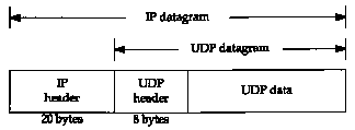
Figure 11.1 UDP encapsulation.
UDP is a simple, datagram-oriented, transport layer protocol: each output operation by a process produces exactly one UDP datagram, which causes one IP datagram to be sent. This is different from a stream-oriented protocol such as TCP where the amount of data written by an application may have little relationship to what actually gets sent in a single IP datagram. Figure 11.1 shows the encapsulation of a UDP datagram as an IP datagram.
RFC 768 [Postel 1980] is the official specification of UDP.
UDP provides no reliability: it sends the datagrams that the application writes to the IP layer, but there is no guarantee that they ever reach their destination. Given this lack of reliability, we are tempted to think we should avoid UDP and always use a reliable protocol such as TCP. After we describe TCP in Chapter 17 we'll return to this topic and see what types of applications can utilize UDP.
The application needs to worry about the size of
the resulting IP datagram. If it exceeds the network's MTU (Section 2.8),
the IP datagram is fragmented. This applies to each network that
the datagram traverses from the source to the destination, not
just the first network connected to the sending host. (We defined
this as the path MTU in Section 2.9.)
We examine IP fragmentation in Section 11.5.
11.2 UDP Header
Figure 11.2 shows the fields in the UDP header.
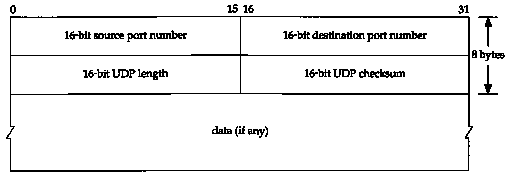
The port numbers identify the sending process and the receiving process. In Figure 1.8 we showed that TCP and UDP use the destination port number to demultiplex incoming data from IP. Since IP has already demultiplexed the incoming IP datagram to either TCP or UDP (based on the protocol value in the IP header), this means the TCP port numbers are looked at by TCP, and the UDP port numbers by UDP. The TCP port numbers are independent of the UDP port numbers.
Despite this independence, if a well-known service is provided by both TCP and UDP, the port number is normally chosen to be the same for both transport layers. This is purely for convenience and is not required by the protocols.
The UDP length field is the length of the
UDP header and the UDP data in bytes. The minimum value for this
field is 8 bytes. (Sending a UDP datagram with 0 bytes of data
is OK.) This UDP length is redundant. The IP datagram contains
its total length in bytes (Figure 3.1),
so the length of the UDP datagram is this total length minus the
length of the IP header (which is specified by the header length
field in Figure 3.1).
11.3 UDP Checksum
The UDP checksum covers the UDP header and the UDP data. Recall that the checksum in the IP header only covers the IP header-it does not cover any data in the IP datagram. Both UDP and TCP have checksums in their headers to cover their header and their data. With UDP the checksum is optional, while with TCP it is mandatory.
Although the basics for calculating the UDP checksum are similar to what we described in Section 3.2 for the IP header checksum (the ones complement sum of 16-bit words), there are differences. First, the length of the UDP datagram can be an odd number of bytes, while the checksum algorithm adds 16-bit words. The solution is to append a pad byte of 0 to the end, if necessary, just for the checksum computation. (That is, this possible pad byte is not transmitted.)
Next, both UDP and TCP include a 12-byte pseudo-header with the UDP datagram (or TCP segment) just for the checksum computation. This pseudo-header includes certain fields from the IP header. The purpose is to let UDP double-check that the data has arrived at the correct destination (i.e., that IP has not accepted a datagram that is not addressed to this host, and that IP has not given UDP a datagram that is for another upper layer). Figure 11.3 shows the pseudo-header along with a UDP datagram.
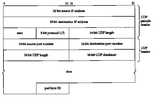
In this figure we explicitly show a datagram with an odd length, requiring a pad byte for the checksum computation. Notice that the length of the UDP datagram appears twice in the checksum computation.
If the calculated checksum is 0, it is stored as all one bits (65535), which is equivalent in ones-complement arithmetic. If the transmitted checksum is 0, it indicates that the sender did not compute the checksum.
If the sender did compute a checksum and the receiver detects a checksum error, the UDP datagram is silently discarded. No error message is generated. (This is what happens if an IP header checksum error is detected by IP.)
This UDP checksum is an end-to-end checksum. It is calculated by the sender, and then verified by the receiver. It is designed to catch any modification of the UDP header or data anywhere between the sender and receiver.
Despite UDP checksums being optional, they should always be enabled. During the 1980s some computer vendors turned off UDP checksums by default, to speed up their implementation of Sun's Network File System (NFS), which uses UDP. While this might be acceptable on a single LAN, where the cyclic redundancy check on the data-link frame (e.g., Ethernet or token ring frame) can detect most corruption of the frame, when the datagrams pass through routers, all bets are off. Believe it or not, there have been routers with software and hardware bugs that have modified bits in the datagrams being routed. These errors are undetectable in a UDP datagram if the end-to-end UDP checksum is disabled. Also realize that some data-link protocols (e.g., SLIP) don't have any form of data-link checksum.
The Host Requirements RFC requires that UDP checksums be enabled by default. It also states that an implementation must verify a received checksum if the sender calculated one (i.e., the received checksum is nonzero). Many implementations violate this, however, and only verify a received checksum if outgoing checksums are enabled.
It is hard to detect whether a particular system has UDP checksums enabled. It is normally impossible for an application to obtain the checksum field in a received UDP header. To get around this, the author added another option to the tcpdump program that prints the received UDP checksum. If this printed value is 0, it means the sending host did not calculate the checksum.
Figure 11.4 shows the output to and from three different systems on our test network (see the figure on the inside front cover). We ran our sock program (Appendix C), sending a single UDP datagram with 9 bytes of data to the standard echo server.
| 1 2 | 0.0 0.303755 ( 0.3038) | sun.1900 > gemini.echo: udp 9 (UDP cksum=6e90) gemini.echo > sun.1900: udp 9 (UDP cksum=0) |
| 3 4 | 17.392480 (17.0887) 17.614371 ( 0.2219) | sun.1904 > aix.echo: udp 9 (UDP cksum=6e3b) aix.echo > sun.1904: udp 9 (UDP cksum=6e3b) |
| 5 6 | 32.092454 (14.4781) 32.314378 ( 0.2219) | sun.1907 > solaris.echo: udp 9 (UDP cksum=6e74) solaris.echo > sun.1907: udp 9 (UDP cksum=6e74) |
We can see from this that two of the three systems have UDP checksums enabled.
Also notice that for this simple example the outgoing datagram has the same checksum as the incoming datagram (lines 3 and 4, 5 and 6). Looking at Figure 11.3 we see that the two IP addresses are swapped, as are the two port numbers. The other fields in the pseudo-header and the UDP header are the same, as is the data being echoed. This reiterates that the UDP checksums (indeed, all the checksums in the TCP/IP protocol suite) are simple 16-bit sums. They cannot detect an error that swaps two of the 16-bit values.
The author also directed a DNS query at each of the eight root name servers described in Section 14.2. The DNS uses UDP primarily, and only two of the eight had UDP checksums enabled!
[Mogul 1992] provides counts of various checksum errors on a busy NFS (Network File System) server that had been up for 40 days. Figure 11.5 summarizes these numbers.
| Layer | Number of checksum errors | Approximate total number of packets |
| Ethernet
IP UDP TCP | 446 14 5 350 | 170,000,000 170,000,000 140,000,000 30,000,000 |
The final column is only the approximate total for each row, since other protocols are in use at the Ethernet and IP layers. For example, not all the Ethernet frames are IP datagrams, since minimally ARP is also used on an Ethernet. Not all IP datagrams are UDP or TCP, since ICMP also uses IP.
Note the much higher percentage of TCP checksum errors
compared to UDP checksum errors. This is probably because the
TCP connections on this system tended to be "long distance"
(traversing many routers, bridges, etc.) while the UDP traffic
was local. The bottom line is not to trust the data-link (e.g.,
Ethernet, token ring, etc.) CRC completely. You should enable
the end-to-end checksums all the time. Also, if your data is valuable,
you might not want to trust either the UDP or the TCP checksum
completely, since these are simple checksums and were not meant
to catch all possible errors.
11.4 A Simple Example
We'll use our sock program to generate some UDP datagrams that we can watch with tcpdump:
| bsdi % sock -v -u -i -n4 svr4 discard connected on 140.252.13.35.1108 to 140.252.13.34.9 |
| bsdi % sock -v -u -i -n4 -w0 svr4 discard connected on 140.252.13.35.1110 to 140.252.13.34.9 |
The first time we execute the program we specify the verbose mode (-v) to see the ephemeral port numbers, specify UDP (-u) instead of the default TCP, and use the source mode (-i) to send data instead of trying to read and write standard input and output. The -n4 option says to output 4 datagrams (instead of the default 1024) and the destination host is svr4. We described the discard service in Section 1.12. We use the default output size of 1024 bytes per write.
The second time we run the program we specify -w0, causing 0-length datagrams to be written. Figure 11.6 shows the tcpdump output for both commands.
| 1 2 3 4 | 0.0 0.002424 ( 0.0024) 0.006210 ( 0.0038) 0.010276 ( 0.0041) | bsdi.1108 > svr4.discard: udp 1024 bsdi.1108 > svr4.discard: udp 1024 bsdi.1108 > svr4.discard: udp 1024 bsdi.1108 > svr4.discard: udp 1024 |
| 5 6 7 8 | 41.720114 (41.7098) 41.721072 ( 0.0010) 41.722094 ( 0.0010) 41.723070 ( 0.0010) | bsdi.1110 > svr4.discard: udp 0 bsdi.1110 > svr4.discard: udp 0 bsdi.1110 > svr4.discard: udp 0 bsdi.1110 > svr4.discard: udp 0 |
This output shows the four 1024-byte datagrams, followed by the four 0-length data-grants. Each datagram followed the previous by a few milliseconds. (It took 41 seconds to type in the second command.)
There is no communication between the sender and receiver before the first datagram is sent. (We'll see in Chapter 17 that TCP must establish a connection with the other end before the first byte of data can be sent.) Also, there are no acknowledgments by the receiver when the data is received. The sender, in this example, has no idea whether the other end receives the datagrams.
Finally note that the source UDP port number changes
each time the program is run. First it is 1108 and then it is
1110. We mentioned in Section 1.9
that the ephemeral port numbers used by clients are typically
in the range 1024 through 5000, as we see here.
11.5 IP Fragmentation
As we described in Section 2.8, the physical network layer normally imposes an upper limit on the size of the frame that can be transmitted. Whenever the IP layer receives an IP datagram to send, it determines which local interface the datagram is being sent on (routing), and queries that interface to obtain its MTU. IP compares the MTU with the datagram size and performs fragmentation, if necessary. Fragmentation can take place either at the original sending host or at an intermediate router.
When an IP datagram is fragmented, it is not reassembled until it reaches its final destination. (This handling of reassembly differs from some other networking protocols that require reassembly to take place at the next hop, not at the final destination.) The IP layer at the destination performs the reassembly. The goal is to make fragmentation and reassembly transparent to the transport layer (TCP and UDP), which it is, except for possible performance degradation. It is also possible for the fragment of a datagram to again be fragmented (possibly more than once). The information maintained in the IP header for fragmentation and reassembly provides enough information to do this.
Recalling the IP header (Figure 3.1), the following fields are used in fragmentation. The identification field contains a unique value for each IP datagram that the sender transmits. This number is copied into each fragment of a particular datagram. (We now see the use for this field.) The flags field uses one bit as the "more fragments" bit. This bit is turned on for each fragment comprising a datagram except the final fragment. The fragment offset field contains the offset of this fragment from the beginning of the original datagram. Also, when a datagram is fragmented the total length field of each fragment is changed to be the size of that fragment.
Finally, one of the bits in the flags field is called the "don't fragment" bit. If this is turned on, IP will not fragment the datagram. Instead the datagram is thrown away and an ICMP error ("fragmentation needed but don't fragment bit set," Figure 6.3) is sent to the originator. We'll see an example of this error in the next section.
When an IP datagram is fragmented, each fragment becomes its own packet, with its own IP header, and is routed independently of any other packets. This makes it possible for the fragments of a datagram to arrive at the final destination out of order, but there is enough information in the IP header to allow the receiver to reassemble the fragments correctly.
Although IP fragmentation looks transparent, there is one feature that makes it less than desirable: if one fragment is lost the entire datagram must be retransmitted. To understand why this happens, realize that IP itself has no timeout and retransmission-that is the responsibility of the higher layers. (TCP performs timeout and retransmission, UDP doesn't. Some UDP applications perform timeout and retransmission themselves.) When a fragment is lost that came from a TCP segment, TCP will time out and retransmit the entire TCP segment, which corresponds to an IP datagram. There is no way to resend only one fragment of a datagram. Indeed, if the fragmentation was done by an intermediate router, and not the originating system, there is no way for the originating system to know how the datagram was fragmented, For this reason alone, fragmentation is often avoided. [Kent and Mogul 1987] provide arguments for avoiding fragmentation.
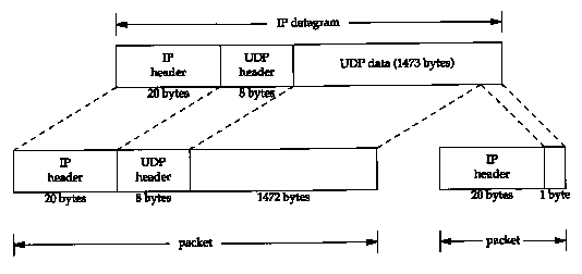
Using UDP it is easy to generate IP fragmentation. (We'll see later that TCP tries to avoid fragmentation and that it is nearly impossible for an application to force TCP to send segments large enough to require fragmentation.) We can use our sock program and increase the size of the datagram until fragmentation occurs. On an Ethernet the maximum amount of data in a frame is 1500 bytes (Figure 2.1), which leaves 1472 bytes for our data, assuming 20 bytes for the IP header and 8 bytes for the UDP header. We'll run our sock program, with data sizes of 1471, 1472, 1473, and 1474 bytes. We expect the last two to cause fragmentation:
| bsdi % sock -u -i -nl -wl471 svr4 discard bsdi % sock -u -i -nl -wl472 svr4 discard bsdi % sock -u -i -nl -wl473 svr4 discard bsdi % sock -u -i -nl -wl474 svr4 discard |
Figure 11.7 shows the corresponding tcpdump output.
| 1 | 0.0 | bsdi-1112 > svr4.discard: udp 1471 |
| 2 | 21.008303 (21.0083) | bsdi.lll4 > svr4.discard: udp 1472 |
| 3 | 50.449704 (29.4414) | bsdi.lll6 > svr4.discard: udp 1473 (frag 26304:1480@0+) |
| 4 | 50.450040 ( 0.0003) | bsdi > svr4: (frag 26304:l@1480) |
| 5 | 75.328650 (24.8786) | bsdi.1118 > svr4.discard: udp 1474 (frag 26313:1480@0+) |
| 6 | 75.328982 ( 0.0003) | bsdi > svr4: (frag 26313:2@1480) |
The first two UDP datagrams (lines 1 and 2) fit into Ethernet frames, and are not fragmented. But the length of the IP datagram corresponding to the write of 1473 bytes is 1501, which must be fragmented (lines 3 and 4). Similarly the datagram generated by the write of 1474 bytes is 1502, and is also fragmented (lines 5 and 6).
When the IP datagram is fragmented, tcpdump prints additional information. First, the output frag 26304 (lines 3 and 4) and frag 26313 (lines 5 and 6) specify the value of the identification field in the IP header.
The next number in the fragmentation information, the 1480 between the colon and the at sign in line 3, is the size, excluding the IP header. The first fragment of both datagrams contains 1480 bytes of data: 8 bytes for the UDP header and 1472 bytes of user data. (The 20-byte IP header makes the packet exactly 1500 bytes.) The second fragment of the first datagram (line 4) contains 1 byte of data-the remaining byte of user data. The second fragment of the second datagram (line 6) contains the remaining 2 bytes of user data.
Fragmentation requires that the data portion of the generated fragments (that is, everything excluding the IP header) be a multiple of 8 bytes for all fragments other than the final one. In this example, 1480 is a multiple of 8.
The number following the at sign is the offset of the data in the fragment, from the start of the datagram. The first fragment of both datagrams starts at 0 (lines 3 and 5) and the second fragment of both datagrams starts at byte offset 1480 (lines 4 and 6). The plus sign following this offset that is printed for the first fragment of both datagrams means there are more fragments comprising this datagram. This plus sign corresponds to the "more fragments" bit in the 3-bit flags in the IP header. The purpose of this bit is to let the receiver know when it has completed the reassembly of all the fragments for a datagram.
Finally, notice that lines 4 and 6 (fragments other than the first) omit the protocol (UDP) and the source and destination ports. The protocol could be printed, since it's in the IP header that's copied into the fragments. The port numbers, however, are in the UDP header, which only occurs in the first fragment.
Figure 11.8 shows what's happening with the third datagram that is sent (with 1473 bytes of user data). It reiterates that any transport layer header appears only in the first fragment.
Also note the terminology: an IP datagram is the unit of end-to-end transmission at the IP layer (before fragmentation and after reassembly), and a packet is the unit of data passed between the IP layer and the link layer. A packet can be a complete IP datagram or a fragment of an IP datagram.
Another variation of the ICMP unreachable error occurs when a router receives a datagram that requires fragmentation, but the don't fragment (DF) flag is turned on in the IP header. This error can be used by a program that needs to determine the smallest MTU in the path to a destination-called the path MTU discovery mechanism (Section 2.9).
Figure 11.9 shows the format of the ICMP unreachable error for this case. This differs from Figure 6.10 because bits 16-31 of the second 32-bit word can provide the MTU of the next hop, instead of being 0.

If a router doesn't provide this newer format ICMP error, the next-hop MTU is set to 0.
The new Router Requirements RFC [Almquist 1993] states that a router must generate this newer form when originating this ICMP unreachable error.
A problem encountered by the author involving fragmentation and this ICMP error is trying to determine the MTU on the dialup SLIP link from the router netb to the host sun. We know the MTU of this link from sun to netb: it's part of the SLIP configuration process when SLIP was installed in the host sun, plus we saw it with the netstat command in Section 3.9. We want to determine the MTU in the other direction also. (In Chapter 25 we'll see how to determine this using SNMP.) On a point-to-point link, it is not required that the MTU be the same in both directions.
The technique used was to run ping on the host solaris, to the host bsdi, increasing the size of the data packets until fragmentation was seen on the incoming packets. This is shown in Figure 11.10.
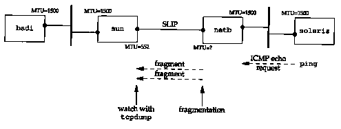
tcpdump was run on the host sun, watching the SLIP link, to see when fragmentation occurred. No fragmentation was observed and everything was fine until the size of the data portion of the ping packet was increased from 500 to 600 bytes. The incoming echo requests were seen (there was still no fragmentation), but the echo replies disappeared.
To track this down, tcpdump was also run on bsdi, to see what it was receiving and sending. Figure 11.11 shows the output.
| 1 | 0.0 | solaris > bsdi: icmp: echo request (DF) |
| 2 | 0.000000 (0.0000) | bsdi > solaris: icmp: echo reply (DF) |
| 3 | 0.000000 (0.0000) | sun > bsdi: icmp: solaris unreachable -
need to frag, mtu = 0 (DF) |
| 4 | 0.738400 (0.7384) | solaris > bsdi: icmp: echo request (DF) |
| 5 | 0.748800 (0.0104) | bsdi > solaris: icmp: echo reply (DF) |
| 6 | 0.748800 (0.0000) | sun > bsdi: icmp: solaris unreachable -
need to frag, mtu = 0 (DF) |
First, the notation (DF) in each line means the don't fragment bit is turned on in the IP header. It turns out that Solaris 2.2 normally turns this bit on, as part of its implementation of the path MTU discovery mechanism.
Line 1 shows that the echo request got through the router netb to sun without being fragmented, and with the DF bit set, so we know that the SLIP MTU of netb has not been reached yet.
Next, notice in line 2 that the DF flag is copied into the echo reply. This is what causes the problem. The echo reply is the same size as the echo request (just over 600 bytes), but the MTU on sun's outgoing SLIP interface is 552. The echo reply needs to be fragmented, but the DF flag is set. This causes sun to generate the ICMP unreachable error back to bsdi (where it's discarded).
This is why we never saw any echo replies on solaris. The replies never got past sun. Figure 11.12 shows the path of the packets.
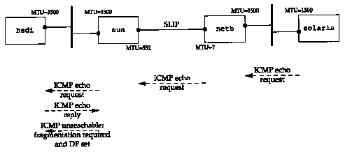
Finally, the notation mtu=0
in lines 3 and 6 of Figure 11.11 indicates that sun
does not return the MTU of the outgoing interface in the ICMP
unreachable message, as shown in Figure 11.9. (In Section 25.9
we return to this problem and use SNMP to determine that the MTU
of the SLIP interface on netb is 1500.)
11.7 Determining the Path MTU Using Traceroute
Although most systems don't support the path MTU discovery feature, we can easily modify a version of traceroute (Chapter 8) to let us determine the path MTU. What we'll do is send packets with the "don't fragment" bit set. The size of the first packet we send will equal the MTU of the outgoing interface, and whenever we receive an ICMP "can't fragment" error (which we described in the previous section) we'll reduce the size of the packet. If the router sending the ICMP error sends the newer version that includes the MTU of the outgoing interface, we'll use that value; otherwise we'll try the next smallest MTU. As RFC 1191 [Mogul and Deering 1990] states, there are a limited number of MTUs, so our program has a table of the likely values and moves to the next smallest value.
Let's first try it from our host sun to the host slip, knowing that the SLIP link has an MTU of 296:
sun % traeeroute.pmtu slip
traceroute to slip (140.252.13.65), 30 hops max
outgoing MTU = 1500
1 bsdi (140.252.13.35) 15 ms 6 ms 6 ms
2 bsdi (140.252.13.35) 6 ms
fragmentation required and DF set, trying new MTU = 1492
fragmentation required and DF set, trying new MTU = 1006
fragmentation required and DF set, trying new MTU = 576
fragmentation required and DF set, trying new MTU = 552
fragmentation required and DF set, trying new MTU = 544
fragmentation required and DF set, trying new MTU = 512
fragmentation required and DF set, trying new MTU = 508
fragmentation required and DF set, trying new MTU = 296
2 slip (140.252.13.65) 377 ms 377 ms 377 ms
In this example the router bsdi does not return the MTU of the outgoing interface in the ICMP error, so we step through the likely values for the MTU. The first line of output for a TTL of 2 prints a hostname of bsdi, but that's because it's the router returning the ICMP error. The final line of output for a TTL of 2 is what we're looking for.
It's not hard to modify the ICMP code on bsdi to return the MTU of the outgoing interface, and if we do that and rerun our program, we get the following output:
sun % traceroute.pmtu slip
traceroute to slip (140.252.13.65), 30 hops max
outgoing MTU = 1500
1 bsdi (140.252.13.35) 53 ms 6 ms 6 ms
2 bsdi (140.252.13.35) 6 ms
fragmentation required and DF set, next hop MTU = 296
2 slip (140.252.13.65) 377 ms 378 ms 377 ms
Here we don't have to try eight different values for the MTU before finding the right one-the router returns the correct value.
As an experiment, this modified version of traceroute was run numerous times to various hosts around the world. Fifteen countries (including Antarctica) were reached and various transatlantic and transpacific links were used. Before doing this, however, the MTU of the dialup SLIP link between the author's subnet and the router netb (Figure 11.12) was increased to 1500, the same as an Ethernet.
Out of 18 runs, only 2 had a path MTU of less than 1500. One of the transatlantic links had an MTU of 572 (a value not even listed as a likely value in RFC 1191) and the router did return the newer format ICMP error. Another link, between two routers in Japan, wouldn't handle a 1500-byte frame, and the router did not return the newer format ICMP error. Setting the MTU down to 1006 did work.
The conclusion we can make from this experiment is
that many, but not all, WANs today can handle packets larger than
512 bytes. Using the path MTU discovery feature will allow applications
to take advantage of these larger MTUs.
11.8 Path MTU Discovery with UDP
Let's examine the interaction between an application using UDP and the path MTU discovery mechanism. We want to see what happens when the application writes datagrams that are too big for some intermediate link.
Since the only system that we've been using that supports the path MTU discovery mechanism is Solaris 2.x, we'll use it as the source host to send 650-byte datagrams to slip. Since our host slip sits behind a SLIP link with an MTU of 296, any UDP datagram greater than 268 bytes (296 -20-8) with the "don't fragment" bit set should cause the router bsdi to generate the ICMP "can't fragment" error. Figure 11.13 shows the topology and the MTUs.
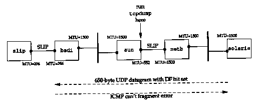
The following command generates ten 650-byte UDP datagrams, with a 5-second pause between each datagram:
solaris % sock -u -i -n10 -w650 -p5 slip discard
Figure 11.14 shows the tcpdump output. When this example was run, the router bsdi was set to not return the next-hop MTU as part of the ICMP "can't fragment" error.
The first datagram is sent with the DF bit set (line 1) and generates the expected error from the router bsdi (line 2). What's puzzling is that the next datagram is also sent with the DF bit set (line 3) and generates the same ICMP error (line 4). We would expect this datagram to be sent with the DF bit off.
On line 5 it appears IP has finally learned that datagrams to this destination should not be sent with the DF bit set, so IP goes ahead and fragments the datagrams at the source host. This is different from earlier examples where IP sends the datagram that is passed to it by UDP and allows the router with the smaller MTU (bsdi in this case) to
| 1 | 0.0 | solaris.38196 > slip.discard: udp 650 (DF) |
| 2 | 0.004218 (0.0042) | bsdi > solaris: icmp:
slip unreachable - need to frag, mtu = 0 (DF) |
| 3 | 4.980528 (4.9763) | solaris.38196 > slip.discard: udp 650 (DF) |
| 4 | 4.984503 (0.0040) | bsdi > solaris: icmp:
slip unreachable - need to frag, mtu = 0 (DF) |
| 5 | 9.870407 (4.8859) | solaris.38196 > slip.discard: udp 650 (frag 47942:552@0+) |
| 6 | 9.960056 (0.0896) | solaris > slip: (frag 47942:106(3552) |
| 7 | 14.940338 (4.9803) | solaris.38196 > slip.discard: udp 650 (DF) |
| 8 | 14.944466 (0.0041) | bsdi > solaris: icmp:
slip unreachable - need to frag, mtu = 0 (DF) |
| 9 | 19.890015 (4.9455) | solaris.38196 > slip.discard: udp 650 (frag 47944:552@0+) |
| 10 | 19.950463 (0.0604) | solaris > slip: (frag 47944:106@552) |
| 11 | 24.870401 (4.9199) | solaris.38196 > slip.discard: udp 650 (frag 47945:552@0+) |
| 12 | 24.960038 (0.0896) | solaris > slip: (frag 47945:1060552) |
| 13 | 29.880182 (4.9201) | solaris.38196 > slip.discard: udp 650 (frag 47946:552@0+) |
| 14 | 29.940498 (0.0603) | solaris > slip: (frag 47946:1060552) |
| 15 | 34.860607 (4.9201) | solaris.38196 > slip.discard: udp 650 (frag 47947:552@0+) |
| 16 | 34.950051 (0.0894) | solaris > slip: (frag 47947:1060552) |
| 17 | 39.870216 (4.9202) | solaris.38196 > slip.discard: udp 650 (frag 47948:552@0+) |
| 18 | 39.930443 (0.0602) | solaris > slip: (frag 47948:106@552) |
| 19 | 44.940485 (5.0100) | solaris.38196 > slip.discard: udp 650 (DF) |
| 20 | 44.944432 (0.0039) | bsdi > solaris: icmp:
slip unreachable - need to frag, mtu = 0 (DF) |
do the fragmentation. Since the ICMP "can't fragment" message didn't specify the next-hop MTU, it appears that IP guesses that an MTU of 576 is OK. The first fragment (line 5) contains 544 bytes of UDP data, the 8-byte UDP header, and the 20-byte IP header, for a total IP datagram size of 572 bytes. The second fragment (line 6) contains the remaining 106 bytes of UDP data and a 20-byte IP header.
Unfortunately the next datagram, line 7, has its DF bit set, so it's discarded by bsdi and the ICMP error returned. What has happened here is that an IP timer has expired telling IP to see if the path MTU has increased by setting the DF bit again. We see this happen again on lines 19 and 20. Comparing the times on lines 7 and 19 it appears that IP turns on the DF bit, to see if the path MTU has increased, every 30 seconds.
This 30-second timer value is way too small. RFC 1191 recommends a value of 10 minutes. It can be changed by modifying the parameter ip_ire_pathmtu_interval (Section E.4). Also there is no way in Solaris 2.2 to turn off this path MTU discovery for a single UDP application or for all UDP applications. It can only be enabled or disabled on a systemwide basis by changing the parameter ip_path_mtu_discovery. As we can see from this example, enabling path MTU discovery when UDP applications write datagrams that will probably be fragmented can cause datagrams to be discarded.
The maximum datagram size assumed by the IP layer on solaris (576 bytes) is not right. In Figure 11.13 we see that the real MTU is 296 bytes. This means the fragments generated by solaris will be fragmented again by bsdi. Figure 11.15 shows the tcpdump output collected on the destination host (slip) for the first datagram that arrives (lines 5 and 6 from Figure 11.14).
| 1 | 0.0 | solaris.38196 > slip.discard: udp 650 (frag 47942:272@0+) |
| 2 | 0.304513 (0.3045) | solaris > slip: (frag 47942:272@272+) |
| 3 | 0.334651 (0.0301) | solaris > slip: (frag 47942:8@544+) |
| 4 | 0.466642 (0.1320) | solaris > slip: (frag 47942:106@552) |
In this example the host solaris should not fragment the outgoing datagrams but should turn off the DF bit and let the router with the smaller MTU do the fragmentation.
Now we'll run the same example but modify the router bsdi to return the next-hop MTU in the ICMP "can't fragment" error. Figure 11.16 shows the first six lines of the tcpdump output.
| 1 | 0.0 | solaris. 37974 > slip.discard: udp 650 (DF) |
| 2 | 0.004199 (0.0042) | bsdi > solaris: icmp:
slip unreachable - need to frag, mtu = 296 (DF) |
| 3 | 4.950193 (4.9460) | solaris.37974 > slip.discard: udp 650 (DF) |
| 4 | 4.954325 (0.0041) | bsdi > solaris: icmp:
slip unreachable - need to frag, mtu = 296 (DF) |
| 5 | 9.779855 (4.8255) | solaris.37974 > slip.discard: udp 650 (frag 35278:272@0+) |
| 6 | 9.930018 (0.1502) | solaris > slip: (frag 35278:272@272+) |
| 7 | 9.990170 (0.0602) | solaris > slip: (frag 35278:114@544) |
Again, the first two datagrams are sent with the DF bit set, and both elicit the ICMP error. The ICMP error now specifies the next-hop MTU of 296.
In lines 5, 6, and 7 we see the source host perform
fragmentation, similar to Figure 11.14. But knowing the next-hop
MTU, only three fragments are generated, compared to the four
fragments generated by the router bsdi
in Figure 11.15.
11.9 Interaction Between UDP and ARP
Using UDP we can see an interesting (and often unmentioned) interaction with UDP and typical implementations of ARP.
We use our sock program to generate a single UDP datagram with 8192 bytes of data. We expect this to generate six fragments on an Ethernet (see Exercise 11.3). We also assure that the ARP cache is empty before running the program, so that an ARP request and reply must be exchanged before the first fragment is sent.
| bsdi % arp -a | verify ARP cache is empty |
| bsdi % sock -u -i -nl -w8192 svr4 discard |
We expect the first fragment to cause an ARP request to be sent. Five more fragments are generated by IP and this presents two timing questions that we'll need to use tcpdump to answer: are the remaining fragments ready to be sent before the ARP reply is received, and if so, what does ARP do with multiple packets to a given destination when it's waiting for an ARP reply? Figure 11.17 shows the tcpdump output.
| 1 | 0.0 | arp who-has svr4 tell bsdi |
| 2 | 0.001234 (0.0012) | arp who-has svr4 tell bsdi |
| 3 | 0.001941 (0.0007) | arp who-has svr4 tell bsdi |
| 4 | 0.002775 (0.0008) | arp who-has svr4 tell bsdi |
| 5 | 0.003495 (0.0007) | arp who-has svr4 tell bsdi |
| 6 | 0.004319 (0.0008) | arp who-has svr4 tell bsdi |
| 7 | 0.008772 (0.0045) | arp reply svr4 is-at 0:0:c0:c2:9b:26 |
| 8 | 0.009911 (0.0011) | arp reply svr4 is-at 0:0:c0:c2:9b:26 |
| 9 | 0.011127 (0.0012) | bsdi > svr4: (frag 10863:800@7400) |
| 10 | 0.011255 (0.0001) | arp reply svr4 is-at 0:0:c0:c2:9b:26 |
| 11 | 0.012562 (0.0013) | arp reply svr4 is-at 0:0:c0:c2:9b:26 |
| 12 | 0.013458 (0.0009) | arp reply svr4 is-at 0:0:c0:c2:9b:26 |
| 13 | 0.014526 (0.0011) | arp reply svr4 is-at 0:0:c0:c2:9b:26 |
| 14 | 0.015583 (0.0011) | arp reply svr4 is-at 0:0:c0:c2:9b:26 |
There are a few surprises in this output. First, six ARP requests are generated before the first ARP reply is returned. What we guess is happening is that IP generates the six fragments rapidly, and each one causes an ARP request.
Next, when the first ARP reply is received (line 7) only the last fragment is sent (line 9)! It appears that the first five fragments have been discarded. Indeed, this is the normal operation of ARP. Most implementations keep only the last packet sent to a given destination while waiting for an ARP reply.
The Host Requirements RFC requires an implementation to prevent this type of ARP flooding (repeatedly sending an ARP request for the same IP address at a high rate). The recommended maximum rate is one per second. Here we see six ARP requests in 4.3 ms.
The Host Requirements RFC states that ARP should save at least one packet, and this should be the latest packet. That's what we see here.
Another unexplained anomaly in this output is that svr4 sends back seven ARP replies, not six.
The final point worth mentioning is that tcpdump was left to run for 5 minutes after the final ARP reply was returned, waiting to see if svr4 sent back an ICMP "time exceeded during reassembly" error. The ICMP error was never sent. (We showed the format of this message in Figure 8.2. A code of I indicates that the time was exceeded during the reassembly of a datagram.)
The IP layer must start a timer when the first fragment of a datagram appears. Here "first" means the first arrival of any fragment for a given datagram, not the first fragment (with a fragment offset of 0). A normal timeout value is 30 or 60 seconds. If all the fragments for this datagram have not arrived when the timer expires, all these fragments are discarded. If this were not done, fragments that never arrive (as we see in this example) could eventually cause the receiver to run out of buffers.
There are two reasons we don't see the ICMP message here. First, most Berkeley-derived implementations never generate this error! These implementations do set a timer, and do discard all fragments when the timer expires, but the ICMP error is never generated. Second, the first fragment-the one with an offset of 0 containing the UDP header-was never received. (It was the first of the five packets discarded by ARP.) An implementation is not required to generate the ICMP error unless this first fragment has been received. The reason is that the receiver of the ICMP error couldn't tell which user process sent the datagram that was discarded, because the transport layer header is not available. It's assumed that the upper layer (either TCP or the application using UDP) will eventually time out and retransmit.
In this section we've used IP fragmentation to see this interaction between UDP and ARP. We can also see this interaction if the sender quickly transmits multiple UDP datagrams. We chose to use fragmentation because the packets get generated quickly by IP, faster than multiple datagrams can be generated by a user process.
As unlikely as this example might seem, it occurs
regularly. NFS sends UDP datagrams whose length just exceeds 8192
bytes. On an Ethernet these are fragmented as we've indicated,
and if the appropriate ARP cache entry times out, you can see
what we've shown here. NFS will time out and retransmit, but the
first IP datagram can still be discarded because of ARP's limited
queue.
11.10 Maximum UDP Datagram Size
Theoretically, the maximum size of an IP datagram is 65535 bytes, imposed by the 16-bit total length field in the IP header (Figure 3.1). With an IP header of 20 bytes and a UDP header of 8 bytes, this leaves a maximum of 65507 bytes of user data in a UDP datagram. Most implementations, however, provide less than this maximum.
"There are two limits we can encounter. First the application program may be limited by its programming interface. The sockets API (Section 1.15) provides a function that the application can call to set the size of the receive buffer and the send buffer. For a UDP socket, this size is directly related to the maximum size UDP datagram the application can read or write. Most systems today provide a default of just over 8192 bytes for the maximum size of a UDP datagram that can be read or written. (This default is because 8192 is the amount of user data that NFS reads and writes by default.)
The next limitation comes from the kernel's implementation of TCP/IP. There may be implementation features (or bugs) that limit the size of an IP datagram to less than 65535 bytes.
The author experimented with various UDP datagram sizes, using the sock program. Using the loopback interface under SunOS 4.1.3, the maximum size IP datagram was 32767 bytes. All higher values failed. But going across an Ethernet from BSD/386 to SunOS 4.1.3, the maximum size IP datagram the Sun could accept was 32786 (that is, 32758 bytes of user data). Using the loopback interface under Solaris 2.2, the maximum 65535-byte IP datagram could be sent and received. From Solaris 2.2 to AIX 3.2.2, the maximum 65535-byte IP datagram could be transferred. Obviously this limit depends on the source and destination implementations.
We mentioned in Section 3.2 that a host is required to receive at least a 576-byte IP datagram. Many UDP applications are designed to restrict their application data to 512 bytes or less, to stay below this limit. We saw this in Section 10.4, for example, where the Routing Information Protocol always sent less than 512 bytes of data per datagram. We'll encounter this same limit with other UDP applications: the DNS (Chapter 14), TFTP (Chapter 15), BOOTP (Chapter 16), and SNMP (Chapter 25).
Just because IP is capable of sending and receiving a datagram of a given size doesn't mean the receiving application is prepared to read that size. UDP programming interfaces allow the application to specify the maximum number of bytes to return each time. What happens if the received datagram exceeds the size the application is prepared to deal with?
Unfortunately the answer depends on the programming interface and the implementation.
The traditional Berkeley version of the sockets API truncates the datagram, discarding any excess data. Whether the application is notified depends on the version. (4.3BSD Reno and later can notify the application that the datagram was truncated.)
The sockets API under SVR4 (including Solaris 2.x) does not truncate the datagram. Any excess data is returned in subsequent reads. The application is not notified that multiple reads are being fulfilled from a single UDP datagram.
The TLI API does not discard the data. Instead a flag is returned indicating that more data is available, and subsequent reads by the application return the rest of the datagram.
When we discuss TCP we'll see that it provides a
continuous stream of bytes to the application, without any message
boundaries. TCP passes the data to the application in whatever
size reads the application asks for-there is never any data loss
across this interface.
11.11 ICMP Source Quench Error
Using UDP we are also able to generate the ICMP "source quench" error. This is an error that may be generated by a system (router or host) when it receives datagrams at a rate that is too fast to be processed. Note the qualifier "may." A system is not required to send a source quench, even if it runs out of buffers and throws datagrams away.
Figure 11.18 shows the format of the ICMP source quench error. We have a perfect scenario with our test network for generating this error. We can send datagrams from bsdi to the router sun across the Ethernet that must be routed across the dialup SLIP link. Since the SLIP link is about 1000 times slower than the Ethernet, we should easily be able to overrun its buffer space. The following command sends 100 1024-byte datagrams from the host bsdi through the router sun to solaris. We send the datagrams to the standard discard service, where they'll be ignored:
bsdi % sock -u -i -w1024 -n100 solaris discard
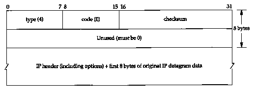
Figure 11.19 shows the tcpdump output corresponding to this command.
| 1 | 0.0 | bsdi .1403 > solaris.discard: udp 1024 |
| 26 lines that we don't show | ||
| 27 | 0.10 (0.00) | bsdi.1403 > solaris.discard: udp 1024 |
| 28 | 0.11 (0.01) | sun > bsdi: icmp: source quench |
| 29 | 0.11 (0.00) | bsdi.1403 > solaris.discard: udp 1024 |
| 30 | 0.11 (0.00) | sun > bsdi: icmp: source quench |
| 142 lines that we don't show | ||
| 173 | 0.71 (0.06) | bsdi. 1403 > solaris.discard: udp 1024 |
| 174 | 0.71 (0.00) | sun > bsdi: icmp: source quench |
We have removed lots of lines from this output; there is a pattern. The first 26 datagrams are received without an error; we show the output only for the first. Starting with our 27th datagram, however, every time we send a datagram, we receive a source quench in return. There are a total of 26 + (74 x 1) = 174 lines of output.
From our serial line throughput calculations in Section 2.10, it takes just over 1 second to transfer a 1024-byte datagram at 9600 bits/sec. (In our example it should take longer than this since the 20 + 8 + 1024 byte datagram will be fragmented because the MTU of the SLIP link from sun to netb is 552 bytes.) But we can see from the timing in Figure 11.19 that the router sun receives all 100 datagrams in less than 1 second, before the first one is through the SLIP link. It's not surprising that we used up many of its buffers.
Although RFC 1009 [Braden and Postel 1987] requires a router to generate source quenches when it runs out of buffers, the new Router Requirements RFC [Almquist 1993] changes this and says that a router must not originate source quench errors. The current feeling is to deprecate the source quench error, since it consumes network bandwidth and is an ineffective and unfair fix for congestion.
Another point to make regarding this example is that our sock program either never received a notification that the source quenches were being received, or if it did, it appears to have ignored them.. It turns out that BSD implementations normally ignore received source quenches if the protocol is UDP. (TCP is notified, and slows down the data transfer on the connection that generated the source quench, as we discuss in Section 21.10.) Part of the problem is that the process that generated the data that caused the source quench may have already terminated when the source quench is received. Indeed, if we use the Unix time program to measure how long our sock program takes to run, it only executes for about 0.5 seconds. But from Figure 11.19 we see that some of the source quenches are received 0.71 seconds after the first datagram was sent, after the process has terminated. What is happening is that our program writes 100 datagrams and terminates. But not all 100 datagrams have been sent-some are queued for output.
This example reiterates that UDP is an unreliable
protocol and illustrates the value of end-to-end flow control.
Even though our sock program successfully
wrote 100 datagrams to its network, only 26 were really sent to
the destination. The other 74 were probably discarded by the intermediate
router. Unless we build some form. of acknowledgment into the
application, the sender has no idea whether the receiver really
got the data.
11.12 UDP Server Design
There are some implications in using UDP that affect the design and implementation of a server. The design and implementation of clients is usually easier than that of servers, which is why we talk about server design and not client design. Servers typically interact with the operating system and most servers need a way to handle multiple clients at the same time.
Normally a client starts, immediately communicates with a single server, and is done. Servers, on the other hand, start and then go to sleep, waiting for a client's request to arrive. In the case of UDP, the server wakes up when a client's datagram arrives, probably containing a request message of some form from the client.
Our interest here is not in the programming aspects of clients and servers ([Stevens 1990] covers all those details), but in the protocol features of UDP that affect the design and implementation of a server using UDP. (We examine the details of TCP server design in Section 18.11.) Although some of the features we describe depend on the implementation of UDP being used, the features are common to most implementations.
What arrives from the client is a UDP datagram. The IP header contains the source and destination IP addresses, and the UDP header contains the source and destination UDP port numbers. When an application receives a UDP datagram, it must be told by the operating system who sent the message-the source IP address and port number.
This feature allows an iterative UDP server to handle multiple clients. Each reply is sent back to the client that sent the request.
Some applications need to know who the datagram was sent to, that is, the destination IP address. For example, the Host Requirements RFC states that a TFTP server should ignore received datagrams that are sent to a broadcast address. (We describe broadcasting in Chapter 12 and TFTP in Chapter 15.)
This requires the operating system to pass the destination IP address from the received UDP datagram to the application. Unfortunately, not all implementations provide this capability.
The sockets API provides this capability with the IP_RECVDSTADDR socket option. Of the systems used in the text, only BSD/386, 4.4BSD, and AIX 3.2.2 support this option. SVR4, SunOS 4.x, and Solaris 2.x don't support it.
We said in Section 1.8 that most UDP servers are iterative servers. This means a single server process handles all the client requests on a single UDP port (the server's well-known port).
Normally there is a limited size input queue associated with each UDP port that a application is using. This means that requests that arrive at about the same time from different clients are automatically queued by UDP. The received UDP datagrams are passed to the application (when it asks for the next one) in the order they were received. It is possible, however, for this queue to overflow, causing the kernel's UDP module to discard incoming datagrams. We can see this with the following experiment. We start our sock program on the host bsdi running as a UDP server:
| bsdi % sock -s -u -v -E -R256 -r256 -P30 6666 | |
| from 140.252.13.33, to 140.252.13.63: 1111111111 | from sun to broad cast address |
| from 140.252.13.34, to 140.252.13.35: 4444444444444 | from svr4, to unicast address |
We specify the following flags: -s to run as a server, -u for UDP, -v to print the client's IP address, and -E to print the destination IP address (which is supported by this system). Additionally we set the UDP receive buffer for this port to 256 bytes (-R), along with the size of each application read (-r). The flag -P30 tells it to pause for 30 seconds after creating the UDP port, before reading the first datagram. This gives us time to start the clients on two other hosts, send some datagrams, and see how the receive queueing works.
Once the server is started, and is in its 30-second pause, we start one client on the host sun and send three datagrams:
sun % sock
-u -v 140.252.13.63 6666
to Ethernet broadcast address
connected on 140.252.13.33.1252 to 140.252.13.63.6666
1111111111
11 bytes of data (with newline)
222222222
10 bytes of data (with newline)
33333333333
12 bytes of data (with newline)
The destination address is the broadcast address (140.252.13.63). We also start a second client on the host svr4 and send another three datagrams:
svr4 % sock -u -v bsdi
6666
connected on 0.0.0.0.1042 to 140.252.13.35.6666
4444444444444
14 bytes of data (with newline)
555555555555555
16 bytes of data (with newline)
66666666
9 bytes of data (with newline)
The first thing we notice in the interactive output shown earlier on bsdi is that only two datagrams were received by the application: the first one from sun with all 1s, and the first one from svr4 with all 4s. The other four datagrams appear to have been thrown away.
The tcpdump output in Figure 11.20 shows that all six datagrams were delivered to the destination host. The datagrams were typed on the two clients in alternating order: first from sun, then from svr4, and so on. We can also see that all six were delivered in about 12 seconds, within the 30-second period while the server was sleeping.
| 1 | 0.0 | sun.1252 > 140.252.13.63.6666: udp 11 |
| 2 | 2.499184 (2.4992) | svr4.1042 > bsdi.6666: udp 14 |
| 3 | 4.959166 (2.4600) | sun.1252 > 140.252.13.63.6666: udp 10 |
| 4 | 7.607149 (2.6480) | svr4.1042 > bsdi.6666: udp 16 |
| 5 | 10.079059 (2.4719) | sun.1252 > 140.252.13.63.6666: udp 12 |
| 6 | 12.415943 (2.3369) | svr4.1042 > bsdi.6666: udp 9 |
We can also see the server's -E option lets it know the destination IP address of each datagram. If it wanted to, it could choose what to do with the first datagram it receives, which was sent to a broadcast address.
We can see several points in this example. First, the application is not told when its input queue overflows. The excess datagrams are just discarded by UDP. Also, from the tcpdump output we see that nothing is sent back to the client to tell it that its datagram was discarded. There is nothing like an ICMP source quench sent back to the sender. Finally, it appears that the UDP input queue is FIFO (first-in, first-out), whereas we saw that the ARP input queue in Section 11.9 was LIFO (last-in, first-out).
Most UDP servers wildcard their local IP address when they create a UDP end point. This means that an incoming UDP datagram destined for the server's port will be accepted on any local interface. For example, we can start a UDP server on port 7777:
sun % sock -u -s 7777
We then use the netstat command to see the state of the end point:
| sun % netstat -a -n -f inet | |||||
| Active Internet connections (including servers) | |||||
| Proto | Recv-Q | Send-Q | Local Address | Foreign Address | (state) |
| udp | 0 | 0 | *.7777 | *.* | |
We have deleted many lines of output other than the one in which we're interested. The -a flag reports on all network end points. The -n flag prints IP addresses as dotted-decimal numbers, instead of trying to use the DNS to convert the address to a name, and prints numeric port numbers instead of service names. The -f inet option reports only TCP and UDP end points.
The local address is printed as *.7777 where the asterisk means the local IP address has been wildcarded.
When the server creates its end point it can specify one of the host's local IP addresses, including one of its broadcast addresses, as the local IP address for the end point. Incoming UDP datagrams will then be passed to this end point only if the destination IP address matches the specified local address. With our sock program, if we specify an IP address before the port number, that IP address becomes the local IP address for the end point. For example,
sun % sock -u -s 140.252.1.29 7777
restricts the server to datagrams arriving on the SLIP interface (140.252.1.29). The netstat output shows this:
| Proto | Recv-Q | Send-Q | Local Address | Foreign Address | (state) |
| udp | 0 | 0 | 140.252.1.29.7777 | *.* |
If we try to send this server a datagram from a host on the Ethernet, bsdi at address 140.252.13.35, an ICMP port unreachable is returned. The server never sees the datagram. Figure 11.21 shows this scenario.
| 1 | 0.0 | bsdi.1723 > sun.7777: udp 13 |
| 2 | 0.000822 (0.0008) | sun > bsdi: icmp: sun udp port 7777 unreachable |
It is possible to start different servers at the same port, each with a different local IP address. Normally, however, the system must be told by the application that it is OK to reuse the same port number.
With the sockets API the SO_REUSEADDR socket option must be specified. This is done by our sock program by specifying the -A option.
On our host sun we can start five different servers on the same UDP port (8888):
| sun % sock -u -s 140.252.1.29 8888 | for SLIP link |
| sun % sock -u -s -A 140.252.13.33 8888 | for Ethernet |
| sun % sock -u -s -A 127.0.0.1 8888 | for loopback interface |
| sun % sock -u -s -A 140.252.13.63 8888 | for Ethernet broadcasts |
| sun % sock -u -s -A 8888 everything else (wildcard IP address) |
All except the first of the servers must be started with the -A flag, telling the system that it's OK to reuse the same port number. The netstat output shows the five servers:
| Proto | Recv-Q | Send-Q | Local Address | Foreign Address | (state) |
| udp | 0 | 0 | *.8888 | *.* | |
| udp | 0 | 0 | 140.252.13.63.8888 | *.* | |
| udp | 0 | 0 | 127.0.0.1.8888 | *.* | |
| udp | 0 | 0 | 140.252.13.33.8888 | *.* | |
| udp | 0 | 0 | 140.252.1.29.8888 | *.* |
In this scenario, the only datagrams that will go to the server with the wildcarded local IP address are those destined to 140.252.1.255, because the other four servers cover all other possibilities.
There is a priority implied when an end point with a wildcard address exists. An end point with a specific IP address that matches the destination IP address is always chosen over a wildcard. The wildcard end point is used only when a specific match is not found.
In all the netstat output that we showed earlier, the foreign IP address and foreign port number are shown as *.* meaning the end point will accept an incoming UDP datagram from any IP address and any port number. Most implementations allow a UDP end point to restrict the foreign address.
This means the end point will only receive UDP datagrams from that specific IP address and port number. Our sock program uses the -f option to specify the foreign IP address and port number:
sun % sock -u -s -f 140.252.13.35.4444 5555
This sets the foreign IP address to 140.252.13.35 (our host bsdi) and the foreign port number to 4444. The server's well-known port is 5555. If we run netstat we see that the local IP address has also been set, even though we didn't specify it:
| Proto | Recv-Q | Send-Q | Local Address | Foreign Address | (state) |
| udp | 0 | 0 | 140.252.13.33.5555 | *.* |
This is a side effect of specifying the foreign IP address and foreign port on Berkeley-derived systems: if the local address has not been chosen when the foreign address is specified, the local address is chosen automatically. Its value becomes the IP address of the interface chosen by IP routing to reach the specified foreign IP address. Indeed, in this example the IP address on sun for the Ethernet that is connected to the foreign address is 140.252.13.33.
Figure 11.22 summarizes the three types of address bindings that a UDP server can establish for itself.
localIP.lport *. lport | *.* *.* | restricted to one client restricted to datagrams arriving on one local interface: localIP receives all datagrams sent to lport |
In all cases, lport is the server's well-known port and localIP must be the IP address of a local interface. The ordering of the three rows in the table is the order that the UDP module applies when trying to determine which local end point receives an incoming datagram. The most specific binding (the first row) is tried first, and the least specific (the last row with both IP addresses wildcarded) is tried last.
Although it's not specified in the RFCs, most implementations allow only one application end point at a time to be associated with any one local IP address and UDP port number. When a UDP datagram arrives at a host destined for that IP address and port number, one copy is delivered to that single end point. The IP address of the end point can be the wildcard, as shown earlier.
For example, under SunOS 4.1.3 we start one server on port 9999 with a wildcarded local IP address:
sun % sock -u -s 9999
If we then try to start another server with the same
wildcarded local address and the same port, it doesn't work, even
if we specify the -A option:
sun % sock -u -s 9999
we expect this to fail
can't bind local address: Address already in use
sun % sock -u-s-A 9999
so we try -A flag this time
can't bind local address: Address already in use
On systems that support multicasting (Chapter 12), this changes. Multiple end points can use the same local IP address and UDP port number, although the application normally must tell the API that this is OK (i.e., our -A flag to specify the SO_REUSEADDR socket option).
4.4BSD, which supports multicasting, requires the application to set a different socket option (SO_REUSEPORT) to allow multiple end points to share the same port. Furthermore each end point must specify this option, including the first one to use the port.
When a UDP datagram arrives whose destination IP
address is a broadcast or multicast address, and there are multiple
end points at the destination IP address and port number, one
copy of the incoming datagram is passed to each end point.
(The end point's local IP address can be the wildcard, which matches
any destination IP address.) But if a UDP datagram arrives whose
destination IP address is a unicast address, only a single copy
of the datagram is delivered to one of the end points.
Which end point gets the unicast datagram is implementation dependent.
11.13 Summary
UDP is a simple protocol. Its official specification, RFC 768 [Postel 1980], requires only three pages. The services it provides to a user process, above and beyond IP, are port numbers and an optional checksum. We used UDP to examine this checksum and to see how fragmentation is performed.
We then examined the ICMP unreachable error that is part of the new path MTU discovery feature (Section 2.9). We watched path MTU discovery using Traceroute and UDP We also looked at the interaction between UDP and ARP whereby most ARP implementations only retain the most recently transmitted datagram to a given destination, while waiting for an ARP reply.
The ICMP source quench error can be sent by a system that is receiving IP datagrams faster than they can be processed. It is easy to generate these ICMP errors using UDP.
11.1 In Section 11.5 we caused fragmentation on an Ethernet by writing a UDP datagram with 1473 bytes of user data. What is the smallest amount of user data that causes fragmentation on an Ethernet if IEEE 802 encapsulation (Section 2.2) is used instead?
11.2 Read RFC 791 [Postel 1981a] to determine why all fragments other than the last must have a length that is a multiple of 8 bytes.
11.3 Assume an Ethernet and a UDP datagram with 8192 bytes of user data. How many fragments are transmitted and what is the offset and length of each fragment?
11.4 Continue the previous exercise, assuming these fragments then traverse a SLIP link with an MTU of 552. You also need to remember that the amount of data in each fragment (i.e., everything other than the IP header) must be a multiple of 8 bytes. How many fragments are transmitted and what is the offset and length of each fragment?
11.5 An application using UDP sends a datagram that gets fragmented into four pieces. Assume that fragments 1 and 2 make it to the destination, with fragments 3 and 4 being lost. The application then times out and retransmits the UDP datagram 10 seconds later and this datagram is fragmented identically to the first transmission (i.e., same offsets and lengths). Assume that this time fragments 1 and 2 are lost but fragments 3 and 4 make it to the destination. Also assume that the reassembly timer on the receiving host is 60 seconds, so when fragments 3 and 4 of the retransmission make it to the destination, fragments 1 and 2 from the first transmission have not been discarded. Can the receiver reassemble the IP datagram from the four fragments it now has?
11.6 How do you know that the fragments in Figure 11.15 really correspond to lines 5 and 6 in Figure 11.14?
11.7 After the host gemini had been up for 33 days, the netstat program showed that 129 IP datagrams out of 48 mi1110n had been dropped because of a bad header checksum, and 20 TCP segments out of 30 mi1110n had been dropped because of a bad TCP checksum. Not a single UDP datagram was dropped, however, because of a UDP checksum error, out of the approximately 18 mi1110n UDP datagrams. Give two reasons why. (Hint: See Figure 11.4.)
11.8 In our discussion of fragmentation we never said what happens to IP options in the IP header-are they copied as part of the IP header in each fragment, or left in the first fragment only? We've described the following IP options: record route (Section 7.3), time-stamp (Section 7.4), strict and loose source routing (Section 8.5). How would you expect fragmentation to handle these options? Check your answer with RFC 791.
11.9 In Figure 1.8 we said that incoming UDP datagrams are demultiplexed based on the destination UDP port number. Is that correct?