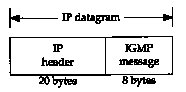
Figure 13.1 Encapsulation of an IGMP message within an IP datagram.
Section 12.4 provided an overview of IP multicasting and described how class D IP addresses are mapped into Ethernet addresses. We briefly mentioned how multicasting occurs on a single physical network, but said complications occur when multiple networks are involved and the multicast datagrams must pass through routers.
In this chapter we'll look at the Internet Group Management Protocol (IGMP), which is used by hosts and routers that support multicasting. It lets all the systems on a physical network know which hosts currently belong to which multicast groups. This information is required by the multicast routers, so they know which multicast datagrams to forward onto which interfaces. IGMP is defined in RFC 1112 [Deering 1989].
Like ICMP, IGMP is considered part of the IP layer.
Also like ICMP, IGMP messages are transmitted in IP datagrams.
Unlike other protocols that we've seen, IGMP has a fixed-size
message, with no optional data. Figure 13.1 shows the encapsulation
of an IGMP message within an IP datagram.
IGMP messages are specified in the IP datagram with
a protocol value of 2.
13.2 IGMP Message
Figure 13.2 shows the format of the 8-byte IGMP message.
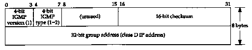
The IGMP version is 1. An IGMP type of 1 is a query sent by a multicast router, and 2 is a response sent by a host. The checksum is calculated in the same manner as the ICMP checksum.
The group address is a class D IP address.
In a query the group address is set to 0, and in a report it contains
the group address being reported. We'll say more about it in the
next section when we see how IGMP operates.
13.3 IGMP Protocol
Fundamental to multicasting is the concept of a process joining a multicast group on a given interface on a host. (We use the term process to mean a program being executed by the operating system.) Membership in a multicast group on a given interface is dynamic-it changes over time as processes join and leave the group.
We imply here that a process must have a way of joining a multicast group on a given interface. A process can also leave a multicast group that it previously joined. These are required parts of any API on a host that supports multicasting. We use the qualifier "interface" because membership in a group is associated with an interface. A process can join the same group on multiple interfaces.
The release of IP multicasting for Berkeley Unix from Stanford University details these changes for the sockets API. These changes are also provided in Solaris 2.x and documented in the ip(7) manual pages.
Implied here is that a host identifies a group by the group address and the interface. A host must keep a table of all the groups that at least one process belongs to, and a reference count of the number of processes belonging to the group.
IGMP messages are used by multicast routers to keep track of group membership on each of the router's physically attached networks. The following rules apply.
Using these queries and reports, a multicast router keeps a table of which of its interfaces have one or more hosts in a multicast group. When the router receives a multicast datagram to forward, it forwards the datagram (using the corresponding multicast link-layer address) only out the interfaces that still have hosts with processes belonging to that group.
Figure 13.3 shows these two IGMP messages, reports
sent by hosts, and queries sent by routers. The router is asking
each host to identify each group on that interface.
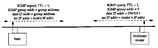
We talk about the TTL field later in this section.
There are many implementation details in this protocol that improve its efficiency. First, when a host sends an initial IGMP report (when the first process joins a group), there's no guarantee that the report is delivered (since IP is used as the delivery service). Another report is sent at a later time. This later time is chosen by the host to be a random value between 0 and 10 seconds.
Next, when a host receives a query from a router it doesn't respond immediately, but schedules the responses for later times. (We use the plural "responses" because the host must send one report for each group that contains one or more members.) Since multiple hosts can be sending a report for the same group, each schedules its response using random delays. Also realize that all the hosts on a physical network receive all the reports from other hosts in the same group, because the destination address of the report in Figure 13.3 is the group's address. This means that, if a host is scheduled to send a report, but receives a copy of the same report from another host, the response can be canceled. This is because a multicast router doesn't care how many hosts belong to the group-only whether at least one host belongs to the group. Indeed, a multicast router doesn't even care which host belongs to a group. It only needs to know that at least one host belongs to a group on a given interface.
On a single physical network without any multicast routers, the only IGMP traffic is the reports issued by the hosts that support IP multicasting, when the host joins a new group.
In Figure 13.3 we noted that the TTL field of the reports and queries is set to 1. This refers to the normal TTL field in the IP header. A multicast datagram with an initial TTL of 0 is restricted to the same host. By default, multicast datagrams are sent with a TTL of 1. This restricts the datagram to the same subnet. Higher TTLs can be forwarded by multicast routers.
Recall from Section 6.2 that an ICMP error is never generated in response to a datagram destined to a multicast address. Multicast routers do not generate ICMP "time exceeded" errors when the TTL reaches 0.
Normally user processes aren't concerned with the outgoing TTL. One exception, however, is the Traceroute program (Chapter 8), which is based on setting the TTL field. Since multicasting applications must be able to set the outgoing TTL field, this implies that the programming interface must provide this capability to user processes.
By increasing the TTL an application can perform an expanding ring search for a particular server. The first multicast datagram is sent with a TTL of 1. If no response is received, a TTL of 2 is tried, then 3, and so on. In this way the application locates the closest server, in terms of hops.
The special range of addresses 224.0.0.0 through 224.0.0.255 is intended for applications that never need to multicast further than one hop. A multicast router should never forward a datagram with one of these addresses as the destination, regardless of the TTL.
In Figure 13.3 we also indicated that the router's
IGMP query is sent to the destination IP address of 224.0.0.1.
This is called the all-hosts group address. It refers to
all the multicast-capable hosts and routers on a physical network.
Each host automatically joins this multicast group on all multicast-capable
interfaces, when the interface is initialized. Membership in this
group is never reported.
13.4 An Example
Now that we've gone through some of the details of IP multicasting, let's take a look at the messages involved. We've added IP multicasting support to the host sun and will use some test programs provided with the multicasting software to see what happens.
First we'll use a modified version of the netstat command that reports multicast group membership for each interface. (We showed the standard netstat -ni output for this host in Section 3.9.) In the following output we show the lines corresponding to multicast groups in a bold font:
| sun % netstat -nia | ||||||||
| Name | Mtu | Network | Address | lpkts | lerrs | Opkts | Oerrs | Coll |
| le0 | 1500 | 140.252.13. | 140.252.13.33 | 4370 | 0 | 4924 | 0 | 0 |
| 224.0.0.1 | ||||||||
| 08;00:20:03:f6:42 | ||||||||
| 01:00:5e:00:00:01 | ||||||||
| sl0 | 552 | 140.252.1 | 140.252.1.29 | 13587 | 0 | 15615 | 0 | 0 |
| 224.0.0.1 | ||||||||
| lo0 | 1536 | 127 | 127.0.0.1 | 1351 | 0 | 1351 | 0 | 0 |
| 224.0.0.1 | ||||||||
The -n option prints IP addresses in numeric format (instead of trying to print them as names), -i prints the interface statistics, and -a reports on all configured interfaces.
The second line of output for le0 (the Ethernet) shows that this interface belongs to the multicast group 224.0.0.1 ("all hosts"), and two lines later the corresponding Ethernet address is shown: 01:00:5e:00:00:01. This is what we expect for the Ethernet address, given the mapping we described in Section 12.4. We also see that the other two interfaces that support multicasting, the SLIP link sl0 and the loopback interface lo0, also belong to the all-hosts group.
We must also show the IP routing table, as the normal routing table is used for multicast datagrams. The bold entry shows that all datagrams for 224.0.0.0 are sent to the Ethernet:
| sun % netstat -rn | |||||
| Routing tables | |||||
| Destination | Gateway | Flags | Refcnt | Use | Interface |
| 140.252.13.65 | 140.252.13.35 | UGH | 0 | 32 | le0 |
| 127.0.0.1 | 127.0.0.1 | UH | 1 | 381 | lo0 |
| 140.252.1.183 | 140.252.1.29 | UH | 0 | 6 | sl0 |
| default | 140.252.1.183 | UG | 0 | 328 | sl0 |
| 224.0.0.0 | 140.252.13.33 | U | 0 | 66 | le0 |
| 140.252.13.32 | 140.252.13.33 | U | 8 | 5581 | le0 |
If you compare this routing table to the one shown in Section 9.2 for the router sun, you'll see that the multicast entry is the only change.
We now run a test program that lets us join a multicast group on an interface. (We don't show any output for our use of this test program.) We join the group 224.1.2.3 on the Ethernet interface (140.252.13.33). Executing netstat shows that the kernel has joined the group, and again the Ethernet address is what we expect. We show the changes from the previous netstat output in a bold font:
| sun % netstat -nia | ||||||||
| Name | Mtu | Network | Address | lpkts | lerrs | Opkts | Oerrs | Coll |
| le0 | 1500 | 140.252.13. | 140.252.13.33 | 4374 | 0 | 4929 | 0 | 0 |
| 224.1.2.3 | ||||||||
| 224.0.0.1 | ||||||||
| 08:00:20:03:f6:42 | ||||||||
| 01:00:5e:01:02:03 | ||||||||
| 01:00:5e:00:00:01 | ||||||||
| sl0 | 552 | 140.252.1 | 140.252.1.29 | 13862 | 0 | 15943 | 0 | 0 |
| 224.0.0.1 | ||||||||
| lo0 | 1536 | 127 | 127.0.0.1 | 1360 | 0 | 1360 | 0 | 0 |
| 224.0.0.1 | ||||||||
We have shown the output again for the other two interfaces, sl0 and lo0, to reiterate that the multicast group is joined only on one interface.
Figure 13.4 shows the tcpdump output corresponding to the process joining the multicast group.
| 1 | 0.0 | 8:0:20:3:f6:42 1:0:5e:1:2:3 ip 60: |
| sun > 224.1.2.3: igmp report 224.1.2.3 [ttl 1] | ||
| 2 | 6.94 (6.94) | 8:0:20:3:f6:42 1:0:5e:1:2:3 ip 60: |
| sun > 224.1.2.3: igmp report 224.1.2.3 [ttl 1] |
Line 1 occurs when the host joins the group. The next line is the delayed report that we said is sent at some random time up to 10 seconds afterward.
We have shown the hardware addresses in these two lines, to verify that the Ethernet destination address is the correct multicast address. We can also see that the source IP address is the one corresponding to sun, and the destination IP address is the multicast group address. We can also see that the reported address is that same multicast group address.
Finally, we note that the TTL is 1, as specified, tcpdump prints the TTL in square brackets when its value is 0 or 1. This is because the TTL is normally greater than this. With multicasting, however, we expect to see lots of IP datagrams with a TTL of 1.
Implied in this output is that a multicast router must receive all multicast datagrams on all its interfaces. The router has no idea which multicast groups the hosts might join.
Let's continue the previous example, but we'll also start a multicast routing daemon on the host sun. Our interest here is not the details of multicast routing protocols, but to see the IGMP queries and reports that are exchanged. Even though the multicast routing daemon is running on the only host that supports multicasting (sun), all the queries and reports are multicast on the Ethernet, so we can see them on any other system on the Ethernet.
Before starting the routing daemon we joined another multicast group: 224.9.9.9. Figure 13.5 shows the output.
| 1 | 0.0 | sun > 224.0.0.4: igmp report 224.0.0.4 |
| 2 | 0.00 ( 0.00) | sun > 224.0.0.1: igmp query |
| 3 | 5.10 ( 5.10) | sun > 224.9.9.9: igmp report 224.9.9.9 |
| 4 | 5.22 ( 0.12) | sun > 224.0.0.1: igmp query |
| 5 | 7.90 ( 2.68) | sun > 224.1.2.3: igmp report 224.1.2.3 |
| 6 | 8.50 ( 0.60) | sun > 224.0.0.4: igmp report 224.0.0.4 |
| 7 | 11.70 ( 3.20) | sun > 224.9.9.9: igmp report 224.9.9.9 |
| 8 | 125.51 (113.81) | sun > 224.0.0.1: igmp query |
| 9 | 125.70 ( 0.19) | sun > 224.9.9.9: igmp report 224.9.9.9 |
| 10 | 128.50 ( 2.80) | sun > 224.1.2.3: igmp report 224.1.2.3 |
| 11 | 129.10 ( 0.60) | sun > 224.0.0.4: igmp report 224.0.0.4 |
| 12 | 247.82 (118.72) | sun > 224.0.0.1: igmp query |
| 13 | 248.09 ( 0.27) | sun > 224.1.2.3: igmp report 224.1.2.3 |
| 14 | 248.69 ( 0.60) | sun > 224.0.0.4: igmp report 224.0.0.4 |
| 15 | 255.29 ( 6.60) | sun > 224.9.9.9: igmp report 224.9.9.9 |
We have not included the Ethernet addresses in this output, because we've already verified that they are what we expect. We've also deleted the notation that the TTL equals 1, because again that's what we expect.
Line 1 is output when the routing daemon starts. It sends a report that it has joined the group 224.0.0.4. Multicast address 224.0.0.4 is a well-known address used by DVMRP (Distance Vector Multicast Routing Protocol), the protocol currently used for multicast routing. (DVMRP is defined in RFC 1075 [Waitzman, Partridge, and Deering 1988].)
When the daemon starts it also sends out a query (line 2). The destination IP address of the query is 224.0.0.1 (all-hosts), as shown in Figure 13.3.
The first report (line 3) is received about 5 seconds later, for group 224.9.9.9. This is the only report received before another query is sent (line 4). These two queries (lines 2 and 4) occur rapidly when the daemon starts up, as it tries to build its multicast routing table.
Lines 5, 6, and 7 are what we expect: one report from the host sun for each group to which it belongs. Notice that the group 224.0.0.4 is reported, in addition to the two groups that we explicitly joined, because as long as the routing daemon is running, it belongs to this group.
The next query on line 8 occurs about 2 minutes after the previous query. Again it elicits the three reports we expect (lines 9, 10, and 11). The reports are in a different order this time, as expected, since the time between receiving the query and sending the report should be randomized.
The final query that we show occurs about 2 minutes
after the previous query, and again we have the expected responses.
13.5 Summary
Multicasting is a way to send a message to multiple recipients. In many applications it is better than broadcasting, since multicasting imposes less overhead on hosts that are not participating in the communication. The simple host membership reporting protocol (IGMP) is the basic building block for multicasting.
Multicasting on a LAN or across closely connected LANs uses the techniques we've described in this chapter. Since broadcasting is often restricted to a single LAN, multicasting could be used instead of broadcasting for many applications that use broadcasting today
A problem that has not been completely solved, however, is multicasting across wide area networks. [Deering and Cheriton 1990] propose extensions to common routing protocols to support multicasting. Section 9.13 of [Periman 1992] discusses some of the problems with multicasting across WANs.
[Casner and Deering 1992] describe the delivery of audio for an IETF meeting across the Internet using multicasting and a virtual network called the MBONE (multicasting backbone).
13.1 We said that hosts schedule IGMP reports with random delays. How can the hosts on a LAN try to ensure that no two hosts generate the same random delay?
13.2 In [Casner and Deering 1992] they mention that UDP lacks two features needed for sending audio samples across the MBONE: detection of packet reordering and detection of duplicate packets. How could you add these capabilities above UDP?